Smart BMS from Greenbikekit

Darren2018

100 W
Joined
Aug 18, 2018
Messages
223
Hi,

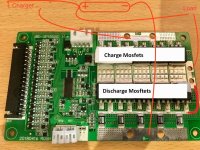
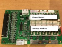
I ordered the Smart BMS from Greenbikekit as 14S and I want to be able to change it to 13S if I need to incase I can't squeeze all 70 cells plus the BMS into the Hailong case. I noticed there is a solder bridge between the balance leads of cells 13 and 14 and was wondering if this has something to do with it as I spoke to GBK and they said it can't be done as they pre config the boards before they send them out, I can't imagine it can't be done via either the hardware or the software but I just need to know how. Here is a pic of the board I have. Also does anyone know how much power will be wasted as heat through these 12X (I'm assuming they are all used for charging/discharging) KIA Semicon Tech KNB3308A FETs on a 52V pack with a 30A load? I want to remove the heatsinks to gain space if I need it but I don't want to burn up the FET's. Here is the data sheet https://lcsc.com/product-detail/MOSFET_KNB3308A_C176861.html
 
I think you might be able to reprogram it.

It looks like this one: https://www.lithiumbatterypcb.com/product/14s-bluetooth-lithium-e-bike-battery-pcb-board-with-30a-constant-charge-and-discharge-current/
LTT Power produces these BMS, so if have a question about programming the BMS you should ask them.

If you have the PC Dongle then you can download the Software from them:
https://www.lithiumbatterypcb.com/smart-bms-software-download/

I do find it strange however that they sell 13S and 14S BMS boards separately, instead of boasting something like ''10S11S12S13S14S BMS'' Like they do with the larger boards. :?:

Also I wouldn't run the BMS without its heatsink with the current Mosfets. I would put in at least 4 or 5 IRFB3077 Mosfets on the B- side
 
I'm not sure if they are the same... I have seen a few variations of this BMS and the one they have pictured is slightly different to mine. I'm worried if I touch anything other than the software that came with it that I will break it due to IC differences or board layout, I read somewhere that different chips need particular pinouts bridged. I don't want to take the chance and unsolder 13-14 and bridge 12-13 as I might destroy it.
 
The new software works with any of the BMS models. I suggest to simply bridge BC3-4 and skip the BC4 balance lead, since you'll short the Battery otherwise. Then reprogram it to 13S in the PC software.

As I have experienced myself, the website still has the pictures of the old BMS. But they do sell the newest ones. If you look at their picture you can see the model on the board JBD-SP15S001 V1.1, the only difference on your board is the V1.4.

But if you are still unsure you can ask them yourself.
 
I'll give it a go. Fingers crossed it does not break. I wasn't sure if you noticed mine was a different revision and I am not really sure about these things :oops:
 
I might also run the pack directly to the controller and skip the BMS. This would let me get rid of the heatsinks without the hassle of replacing the FET's and loose a bit of resistance. If I use it just for charging/balancing this should be ok right?
 
If you really wanna lose discharge protection then sure. What you could do is solder a thick wire from the Mosfet legs to P-. This way you still have overcharge protection and the current is still measured by the BMS which will allow you to see when the Battery's empty.
 
Nope, since you are using the C- side to charge.

Also you can buy like two 3077 on ebay and add them in on the underside of the PCB and keep undercharge protection also.

You don't have to remove the old Mosfets. I was just suggesting that, if I was doing it. I'm guessing you want to keep costs down?
 
Undercharge protection is there so none of the cells fall under 2.5V or so. That's what the Balance wires are there for, not just balancing but also monitoring each cell individually.
 

Attachments

  • IMG_3098(1).jpg
    IMG_3098(1).jpg
    101.7 KB · Views: 2,836
I didn't realise until now there are 3 connections to be made, this is ideal combined with your idea! I wondered why I had so many FET's and why you were saying I needed more :oops: :lol:
 
eee291 said:
Nope, since you are using the C- side to charge.

Also you can buy like two 3077 on ebay and add them in on the underside of the PCB and keep undercharge protection also.

You don't have to remove the old Mosfets. I was just suggesting that, if I was doing it. I'm guessing you want to keep costs down?


It's not so much the cost but more the difficulty of trying to remove them with a low powered iron.
 
Like I said you don't need to remove them, you still have 4 unused pads on the B- side, so you can just add more and leave the old ones on there.

I just use some cheap 100w soldering iron like this one:https://www.ebay.co.uk/itm/100W-High-Power-Soldering-Iron-Stained-Glass-Making-Tiffany-Lamp-Art-Repair/252612286434?epid=523572396&hash=item3ad0dd97e2:g:D-YAAOSwTM5Y6NcY
 
Awesome! If I added more FET's would I need just another 4 for the discharge side? Will it matter that the spec's will be different? Won't the 4 I add take more load than others and thus heat up more?
 
4 3077 Mosfets could handle the full 30A on their own. But since all Mosfets are in parallel, some of the load also goes to the other Mosfets as well.
 
Hi everyone.

I also have purchased one of these Chinese BMS although one with more KNB3308A slapped on the board so no free solder tabs.

It looks exactly the same as this in every other regard though.

Have a couple of questions, firstly where is the best software to control it via the UART to USB module?

(and I guess via the bluetooth but that is less urgent)

I downloaded the one from greenbikekit but many of the buttons are in Chinese, In particular the help tab which doesn't bode well.

Even just a guide in how to use it with a few of the features explained.

also I am curious about adding more KNB3308A in parallel as I want/need to over run this module as I just ordered one of the tangent 6kw motors and so I will need to go 30A over its rated current.

Plus I like a bit of a safety factor as I have often found this kind of hardware does not have that built in.

If I take out a lead wire from the 3 pins to a second board with a few more stacked on it should I expect to have any problems?

I would need to put extra R004 on the board too. Looks pretty clear that every 3308 that is added requires one more.

any help would be highly appreciated as I am a little out of my depth here.

Regards, Nick.
 
Back
Top