circuit said:EDIT3: okay, It's alive. Virtualbox+windowsXP... BMS ir working from first try. Some measurement around 15mV off.
circuit said:... I get only "unknown device". Any suggestions? Where do I get a driver?
100years later: driver
circuit said:EDIT3: okay, It's alive. Virtualbox+windowsXP... BMS ir working from first try. Some measurement around 15mV off.
circuit said:... I get only "unknown device". Any suggestions? Where do I get a driver?
exco said:circuit said:EDIT3: okay, It's alive. Virtualbox+windowsXP... BMS ir working from first try. Some measurement around 15mV off.
circuit said:... I get only "unknown device". Any suggestions? Where do I get a driver?
100years later: driver
") thanks
thanksfriendly1uk said:It's not OR pal. Everything tags to the P+
Balance plug last, as if the balance plug is connected while the chips not powered, it smokes.

friendly1uk said:There is no need to disconnect the controller while charging. The only connection/disconnection you need make is plugging and unplugging the charger. That is of course unless you wish to leave the controller on the bike and walk off with the battery. In which case another plug would be required.
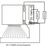
This is how my latest pack is wired. It stays on the bike.
View attachment 1
Another allowing the controller and battery to split. It is the same as the bmsb drawing, but laid out how I would physically wire it.
Thus, you keep the cells and bms together, and may separate the charger and the controller. Though there is no electrical need to isolate the controller while charging. It just makes getting the pack off the bike easier.
friendly1uk said:I hope I have boosted your confidence then pal
The connection order is not widely published. It has caused a few losses. The charger point is not adequately protected against short circuits either. Checking it regularly is not a high enough priority in the software, though that can be adjusted if you have the pc link. Good boards other than that.
If your not using the full 13s capability then it's worth checking they assembled it properly. The top cell needs connecting to vcc via a resistor which is often not done. The board is made with it connected to 13, but when 13 is not used the board needs altering. I have not seen bmsb do this.
I don't quite recall the job. I think it is R1. The board has what look like test points along the ballance plug that enable 13 to be easily hooked to the new highest cell. Number 12 when I got a 12s board.
and not fully charged (max cell) near BMS OverVoltage Threshold as well, I assume?chayr said:not full disharged.
chayr said:I Try to decrease the charger voltage already with the screw in the charger but it doesn't work and now I have one wonky charger
Because I set the 3 screw in the charger to try to shut down voltage.
Sorry for disturb this topic.dnmun said:if you post up the voltages in your own thread we can show you how to make the battery balance if you can do stuff yourself.
Then B0, B1, B2... B13. Another sequence will kill the chip (I think...).
crumly said:
Depends on what you want to do achieve.altermontrealiste said:what about using 2 of those bms's in series? Finding a bms that does 18s and 20s is hard...
thanks
friendly1uk said:I don't see why full functionality of two boards in series would be a problem. Both boards would need fets that take full pack voltage and the charger control circuits could be mingled with optical isolation and a comparitor. I think the fets should be addressed by mingling there output by the same means, to drive external fets that can take a lot more power to aid more people here.
Why don't you think lvc would work on the top pack? Am I missing something in my permanently drunken state