
You are using an out of date browser. It may not display this or other websites correctly.
You should upgrade or use an alternative browser.
You should upgrade or use an alternative browser.
Control box
- Thread starter ELOR
- Start date
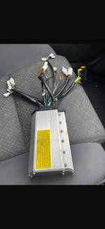
They were pics already in my phone I didn’t think I’ll be able to work the site out like communicate with people. I didn’t think the msg will go through. I got no idea who I sent them to. I’ll take sum pics in a couple hrs and maybe sumone can helpNot based on those pictures. Maybe if you separated all of the connectors so the wire colors and number of wires for each are visible in the pics.
M
Measure the voltage and then what. So ur saying the throttle wires should read voltage and the rest won’t. What should they read how much voltageThrottle’s easy to find. Just power it up and measure voltages on three pin connectors.
You’re looking for 5v, earth, and one other. Neutral is rarely anything other than black, and easy to find - put your meter’s negative on it and probe for pack voltage on red/orange wires. If you find pack voltage, you have your earth. Leave your meter on this earth, and probe for a 5V wire.
You can also open up the controller cases to see what the PCB labels say.
You can also open up the controller cases to see what the PCB labels say.
ok I will try that soon and go from there. I’m going to have to wire the whole bike up so it’s going to have to go to someone that can do it or if anyone knows any mobile mechanic or auto electrician that can do it for me. Or anyone else who is experienced enough because the way I’m going it’s not going to ever finsh. Thanks for your help much appreciated. Mate I’m having hard time using this site. lol. First time I’ve used anything like this but it’s brilliant if you know how to use it properly. I don’t know if it’s Australia or state wide or International But I’m in Sydney Australia if anyone knows someone that can do a little wiring. Cheers thanks for your help.You’re looking for 5v, earth, and one other. Neutral is rarely anything other than black, and easy to find - put your meter’s negative on it and probe for pack voltage on red/orange wires. If you find pack voltage, you have your earth. Leave your meter on this earth, and probe for a 5V wire.
You can also open up the controller cases to see what the PCB labels say.
Fairly easy with pics.M
Measure the voltage and then what. So ur saying the throttle wires should read voltage and the rest won’t. What should they read how much voltage
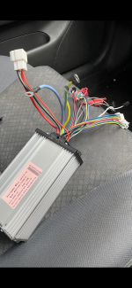
What he's saying is that you can determine, from the available 3 conductor connectors, or the three loose wires in the first pic, you can identify with a meter a 5V conductor, a ground conductor, and signal wire, which could be throttle or PAS, or ground and two signal wires for a three speed switch, or at least an educated guess. And then to test them without frying your 5V supply.
Yes, E-HP explains things better.
You can quickly narrow the considered set by eliminating the motor wires, earth wires, and high voltage wires.
There’s only one wire specific to the throttle. The other two required for its operation, ground and 5V, for convenience will typically be bundled with this throttle wire on a three pin socket, but if not they can be taken from wherever you can find them.
Once you have 5V and ground connected to your throttle you can reasonably safely hook up the third throttle wire to the few remaining mystery controller wires and give the throttle a twirl (with your meter connected to measure the voltage signal on the third throttle wire).
If you stay clear of high (battery) voltage wires, sparks will not fly. Can’t guarantee that you won’t destroy the controller in the process, but if it’s a choice between that and leaving the controller to gather dust, then you might as well roll the dice.
Opening the controller case might save time. The throttle wire pin might be labelled SP. Then again, it might not.
lol I feel ya. All I can do is try and if it works great if not great. Not the end of my journey. Thanks heaps much appreciatedYes, E-HP explains things better.
You can quickly narrow the considered set by eliminating the motor wires, earth wires, and high voltage wires.
There’s only one wire specific to the throttle. The other two required for its operation, ground and 5V, for convenience will typically be bundled with this throttle wire on a three pin socket, but if not they can be taken from wherever you can find them.
Once you have 5V and ground connected to your throttle you can reasonably safely hook up the third throttle wire to the few remaining mystery controller wires and give the throttle a twirl (with your meter connected to measure the voltage signal on the third throttle wire).
If you stay clear of high (battery) voltage wires, sparks will not fly. Can’t guarantee that you won’t destroy the controller in the process, but if it’s a choice between that and leaving the controller to gather dust, then you might as well roll the dice.
Opening the controller case might save time. The throttle wire pin might be labelled SP. Then again, it might not.
Similar threads
- Replies
- 3
- Views
- 255
- Replies
- 2
- Views
- 121
- Replies
- 15
- Views
- 213
- Replies
- 4
- Views
- 351