Converting a hubmotor to a middrivemotor

spinningmagnets,

I second the impact driver. Works great on Phillips screws. They are notorious for stripping/slipping, especially if Loctited.

As a sprocket adaptor, if you are using the original 12 mm axle with the big flats on it, an adaptor similar to the Staton one, but with a 12 mm ID, and two 6 mm set screws run down onto the flats will work great.

I made a simple torque arm from a piece of 1/2" x 1" aluminum bar stock once. I put a 12 mm hole through one end, and drilled and tapped through either side for 6 mm set screws. Much easier to make than a rectangular hole, and actually a tighter fit.
 
Set screws aren't that great, I also tried that without success. A solid piece that fits the shafts shape can conduct torque much better. Is there anyone who would use set screws for his Hubmotor torque arms?? :lol:

I make my improved sprocket adapter from multiple 3mm sheet, using a hole saw, a 10mm drill, I use the shimano nexus geared hub sprockets with my adpater.... these are 2mm wide (perfect as an output sprocket) with stamped dogs, which makes it fit on a 3mm hub.

sprocket.jpg

http://www.utahtrikes.com/uploads/utupgrades/11615586/picture1/sprocket.jpg

As a first step I make 3 round plate with 6mm initial center hole for the hole saw.

I take one of these round plates, file it down a bit and I file pockets into it, so that the Nexus sprocket fits onto it. I use 2 more round plates made of 3mm steel for aligning the nexus sprocket axially on both sides. I use a 6mm screw through the center holes to center all three plates/round sheets. Then I drill 3 holes into the adapter and screw itall together with nuts. Then I drill the 6mm initial center holes to 10mm. After that, I widen with a file so i fit's onto the 12mm oval shaft, I use a Bafang torque arm as a stencil.

I'll post some picture when i'm home again, I didn't need a lathe for this. It could be made using a waterjet, laser cutting, plasma cutting etc. If there would be enough people who are interested, it could be very cheap to make.
 
Hi,

crossbreak said:
Greenmachine uses the same setup as me, he installed a freewheel on the left side of the motor. Does not depend on where you place the motor, you always need a freewheel for the cranks. You can either install it at the cranks itself (fails due too much torque, freewheels are not made for these high loads) or at the motor which works great.
The reason high qaulity FW's normally fail on the cranks is the load placed by pedaling while the FW is freewheeling.

mr.electric said:
Behind the bb is best but there is no room on most frames. Ahead of the bb and you have to deal with a freewheel crank. (except cross breaks' bike)
In addition to eliminating the freewheel cranks a major advantage of crossbreaks' configuration that it doesn't require gearing down to crank RPM, which then gets geared up to rear wheel RPM.

I agree that behind the bb is cleanest solution but I don't see the advantage of the left-side driven configuration, as opposed to the same configuration driven on the right.
Here's his layout:
CrossFrameDiagram.png

The picture below is intended to show the same chain from a fixed sprocket on the motor shaft to the rear sprocket plus a chain on the right from the chain-rings to a FW on the right end of the motor shaft. This will allow using standard bb/crank parts, although it might require using cranks designed with space for dual chain-rings to accommodate the second chain on the right side.
CrossFrameRightDriveDiagram.jpg
 
There is still some discussion about all of the contributing factors that make a freewheel wear out faster when it is used in a freewheeling crank, (like the GNG). I don't think it is one single cause, but several factors. I could be wrong, but...the type of bracket that would attach a converted MAC in that place would allow the individual builder to use a crossbreak-style left chainring, or a familiar "two-chainring" BB-drive, like the Cyclone or GNG. Each bracket purchaser would have the choice.

Here's my opinion on this new optional configuration.

edit: The phase and hall wires exit from the case-sideplate instead of the hollow shaft. This means that repairs, phase-wire upgrades, and temp-probe installment is an easy and quick job.

The Hollow-tech BB-shaft will provide a solid base for jumping a bike using a hardtail frame. The stock square-taper GNG BB (using a cartridge from their "affordable" parts line) is barely adequate for a street commuter on a full suspension. I think the 19mm Trials/BMX Cromo-tube BB-shafts are also a great option.

When using a single chain on the freewheel on the left side, it should last years. BB-drives have a longevity issue with FWs that has yet to be proven as solved. With the FW on the left side, it will never feel any motor torque, and since it's freewheeling at the output shaft RPMs (after the 6:1 motor reduction), even the freewheeling wear on the pawls/springs will be light.

With two chainrings on the right (mounted to the crank-arm), BB-shaft space is at a premium, and there is very little leeway for adjusting the chainline. With a freewheel on the left and a motor-sprocket on the right, I realize that only a small amount adjust-ability is helped, but...sometime a small improvement is all it takes (the motor mount and the right-side sprocket can both be shimmed in or out).

If someone raises the volts on a BB-drive, the builder is often unable to add pedaling to the bike at its top speed. This is not an issue for everyone, but for a few builders, it's nice to know that even if they go to 72V, they can easily find a chainring for the right side that will put their 70-80 cadence back near the motors top-speed.

The GNG is only available in one Kv, the MAC (converted or not) is available in 5 Kvs...and it also has more copper mass. The crossbreak-style mount uses small enough sprockets, so that a builder can commit to this design and know that...they could go wild with an extra high voltage system, and if needed...they could still have the option to change the Kv and/or the sprocket size in the future (if...pedal cadence at high motor RPMs was important to you).

edit: from Mitch: "a major advantage of crossbreaks' configuration is that it doesn't require gearing [the motor] down to crank RPMs, which then gets geared up to rear wheel RPMs"

edit: another advantage is that the freewheels in the system are the common variety, instead of the flanged-style that must be ordered, waited for, and may not be in stock when you most need one...

edit: many builders have resorted to an 11T gear cluster on the rear wheel to get speeds up higher and sometimes to also help pedal-cadence. As Chalo pointed out, this puts tremendous stress on each one of the 5 teeth that are fully engaged by the chain. This configuration allows a 15T as the smallest sprocket (or more?), which would provide 7 fully engaged teeth. Two more out of 5 = 40% improvement in individual tooth wear and peak chain holding power before skipping occurs (all numbers approximate, of course).

edit: The GNG has 40mm between the center of the motor-shaft and the stator gap (where the magnetic interaction applies force to the rotor). The MAC has 68mm from shaft to gap, which provides 70% more leverage (torque?) to the rotor per watt applied. This partially because the MAC simply has a larger diameter, and also because the MAC is an outrunner instead of an inrunner like the GNG.

I don't think this configuration is for everyone, but I think a few builders will like it if they try it...
 
Hi,

crossbreak said:
You can either install it at the cranks itself (fails due too much torque, freewheels are not made for these high loads)
spinningmagnets said:
There is still some discussion about all of the contributing factors that make a freewheel wear out faster when it is used in a freewheeling crank, (like the GNG). I don't think it is one single cause, but several factors.

When using the freewheel on the left side, it should last years.
Well, as you point out, we know it isn't excessive torque since even cheap fw's work well in matt's extremely high powerful left hand drives.

Is the following a response to my suggested right side configuration?
spinningmagnets said:
When using the freewheel on the left side, it should last years. BB-drives have a longevity issue with FWs that has yet to be proven as solved.
Because my suggestion doesn't require a bb fw.

spinningmagnets said:
With two chainrings on the right, BB-shaft space is at a premium, and there is very little leeway for adjusting the chainline. With a freewheel on the left and a chainring on the right, I realize only a small amount of shaft space is helped, but...sometime a small improvement is all it takes.
No more space is required than for an ecospeed or cyclone which seem to work on almost every bike.

spinningmagnets said:
If someone raises the volts on a BB-drive, the builder is often unable to add pedaling to the bike at its top speed. This is not an issue for everyone, but for a few builders, it's nice to know that even if they go to 72V, they can easily find a chainring for the right side that will put their cadence back near the motors top-speed.

The GNG is only available in one Kv, the MAC (converted or not) is available in 5 Kvs...and it also has more copper mass. The crossbreak-style mount uses small enough sprockets so that a builder can commit to this design and know that they could get insane with an extra high voltage system, and if needed...they could change the Kv and/or the sprocket size in the future (if...pedal cadence at high motor RPMs was important to you).
My suggestion is identical in this respect.
 
I apologize, Mitch. I thought I understood your post at first. I now realize I read it too fast. I think you are right, and that is an interesting option.

edit:
a major advantage of crossbreaks' configuration that it doesn't require gearing down to crank RPM, which then gets geared up to rear wheel RPM.

In all this time, I've had so much on my mind that this had completely escaped my notice until just now, since you pointed it out. Thanks for that!
 
Hi,

MitchJi said:
a major advantage of crossbreaks' configuration that it doesn't require gearing down to crank RPM, which then gets geared up to rear wheel RPM.

spinningmagnets said:
In all this time, I've had so much on my mind that this had completely escaped my notice until just now, since you pointed it out.

This raises the target loaded motor output rpm to match cadence to something like 200-300 rpm instead of 80-100.

For example an Alfine 8 with a 20t sprocket and a 50t chain-ring unpowered looks like this:
http://www.sheldonbrown.com/gears/internal.html
Alfine8-26inch-80rpm-both.png

If we used two 20t sprockets on the motor, one connected to the chain-ring and one connected to the rear sprocket unpowered pedaling would be the identical. To match a cadence of 80 we'd need a motor rpm of 200 or for a cadence of 100 we'd need 250.

The 25 mph top speed is a little low but with a top speed of 8.2 mph in first gear with a 50V/50A (2.5kw) Mac motor spinning internally at 1,200 rpm you could almost pull out a small stump :).
 
LOL! With my first gear top speed on my MAC mid drive, of 12 MPH (TESTED) at only 1200 watts I could pull out a small stump, with that combo you could pull a small house down! LOL!
 
spinningmagnets said:
a major advantage of crossbreaks' configuration that it doesn't require gearing down to crank RPM, which then gets geared up to rear wheel RPM.

In all this time, I've had so much on my mind that this had completely escaped my notice until just now, since you pointed it out. Thanks for that!

Hey FINALLY someone got what I tried to tell all the time... :p I even wrote a wiki article about these pros and cons:
http://endless-sphere.com/w/index.php/EBike_Motors_Middrive#Jackshaft_Dual_Freewheel_Config
 
BMC, I was PM'd by Ilia at ebikessf.com, and the loaded speed of their two Kvs using 26" wheel at 50V is 27-MPH and 30-MPH, soooo...wheel RPMs would then be: 349-RPMs for "torque" model, and 388-RPMs for the "Cruiser" model.

Add about 15% for unloaded speed (wheel in the air, all numbers approximate) shell RPMs are 401 and 446 @ 50V, so 5:1 reduction means motor RPMs are 2005 and 2230...Kv is roughly 40 and 44...very similar to MAC 10T and 8T

It appears the BMC with thinner laminations (0.35mm on BMC vs 0.50mm on Bafang/MAC...28% improvement) can take almost double the RPM's before it begins making significant eddy-current waste-heat (I think the curve is squared instead of linear?). I still have a lot to learn. I will post corrections and new info as soon as I can. Any assistance with eddy-currents and waste-heat efficiency curves appreciated (ES is very big, sometimes difficult to find the answer to a question that is new to me).

xxxxxxxxxxxxxxxxxxxxxxxxxxxxxxxxxxxxxxxxxxxxxxxxxxxxxxxxxxxxxxxxxxxx
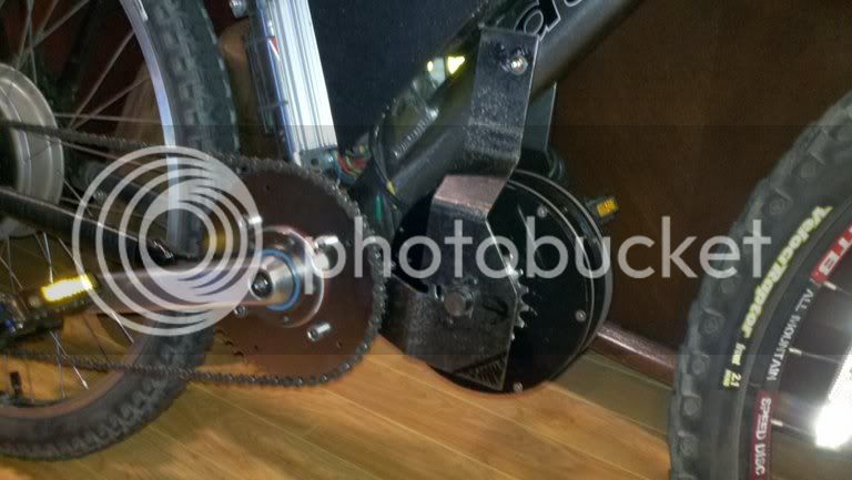
As far as using the MAC as a geared hub to convert, there is a chance the only acceptable version are the 10T/12T when using 36V, and the 12T only when using 44V/48V.

At 36V, 10T motor-RPM is 1275, 12T is 1,000 At 48V, 12T is 1,300-RPM

A 1,300-RPM motor that is geared to pull a bike at 10-MPH in low gear will be a very good hill-climber, when compared to a one-speed motor that is spinning at wheel-RPMs, for example, at 10-MPH a 26-inch wheel is turning 129-RPM, a slow-winding Direct-Drive hub (9C, etc) has the copper mass to absorb and shed a lot of heat on a slow uphill, but adding gears to a motors output will keep the motor-RPMs high and in the middle of its efficiency range so we can avoid making most of that waste heat in the first place. An internally-geared hub (MAC, BMC, Bafang) will spin the motor 5 times the speed of the wheel, but at low wheel speeds, the motor-RPMs are still too low for best performance, and the copper mass is much less than the common DD-hubs.

xxxxxxxxxxxxxxxxxxxxxxxxxxxxxxxxxxxxxxxxxxxxxxxxxxxxxxxxxxx

edit: because Bafang motor has only 16 poles (8 pole-pairs) they can run twice the RPMs as the MAC even though they have the less-desireable thicker 0.50mm laminations. Good news, the bare motor can be bought for less than $130 (I have no experience with this vendor)

greenbikekit.com has Bafang (at 36V they have 216-RPM and 312-RPM) for $124
http://www.greenbikekit.com/index.php/electric-motor/bldc-bpm-500w-36v.html
 
Hi,

MitchJi said:
A major advantage of crossbreaks' configuration that it doesn't require gearing down to crank RPM, which then gets geared up to rear wheel RPM.
crossbreak said:
Hey FINALLY someone got what I tried to tell all the time... :p I even wrote a wiki article about these pros and cons:
crossbreaks-wiki said:
Advantages over Freewheel-Crankset configs:
* less torque at the pedal side freewheel
* additional overdrive makes using smaller chainwheels possible
* no bending/twisting loads on the freewheels
* lower Q-factors possible (Q-factor is the distance between the pedals [24])
* using HollowTech2 cranks is possible, since there is no need for special BSA threaded freewheel cranks. HollowTech2 Bottom Brackets can be fitted to any Bottom Bracket length between 68-78mm. Adding a stiff motor mount that engages on both sides of the Bottom Bracket is much more simple than for the Freewheel crank solution
I just read it and I don't see that mentioned.

MitchJi said:
The 25 mph top speed is a little low but with a top speed of 8.2 mph in first gear with a 50V/50A (2.5kw) Mac motor spinning internally at 1,200 rpm you could almost pull out a small stump :).
spinningmagnets said:
A 1,300-RPM motor that is geared to pull a bike at 10-MPH in low gear will be a very good hill-climber, when compared to a one-speed motor that is spinning at wheel-RPMs, for example, at 10-MPH a 26-inch wheel is turning 129-RPM
Yes!

Whiplash said:
LOL! With my first gear top speed on my MAC mid drive, of 12 MPH (TESTED) at only 1200 watts I could pull out a small stump, with that combo you could pull a small house down! LOL!
The main potential issue is how would it handle a sustained 35mph (uphill) if it was geared up accordingly?

spinningmagnets said:
As far as using the MAC as a geared hub to convert, there is a chance the only acceptable version are the 10T/12T when using 36V, and the 12T only when using 44V/48V.

At 36V, 10T motor-RPM is 1275, 12T is 1,000

At 48V, 12T is 1,300-RPM
Did you forget the 5:1 (6:1 converted) reduction?
em3ev.com said:
http://em3ev.com/store/index.php?route=product/product&path=40&product_id=52
Specification:
6 turn high speed motor - 400rpm loaded at 36V [332RPM-461RPM]

7 turn high speed motor- 350rpm loaded at 36V [292RPM-406RPM]

8 turn standard motor - 320rpm loaded at 36V [266RPM-370RPM]

10 turn torque motor - 255rpm loaded at 36V [214RPM-297RPM]

12 turn low speed extra torque motor - 200rpm loaded at 36V [166RPM-231RPM]
I added the figures in brackets figured for 6:1 vs 5:1 for 36V. The higher figure is for 50V at 6:1.

The 6:1 vs 5:1 advantage of this motor setup is sweet (Danke schön crossbreak :D )!
MitchJi said:
If we used two 20t sprockets on the motor, one connected to the chain-ring and one connected to the rear sprocket unpowered pedaling would be the identical. To match a cadence of 80 we'd need a motor rpm of 200 or for a cadence of 100 we'd need 250.
With that configuration and two 16t sprockets on the motor (13-24 teeth available), and using 24t in the rear hub our target RPM's become 300 and 375 (we'd need to decrease the chain-ring size also) so at 50V an 8T MAC seems easy and the 7T looks feasible.

For a more conventional motor driving cranks with a FW you could use a 13T FW on the motor driving a 52t chain-ring so at 50V an 8T MAC (92RPM) seems easy and the 7T might be feasible.

Note: Even though the "conventional motor driving cranks" configuration requires a lot more reduction that isn't a huge disadvantage because you have an additional stage for obtaining reduction built- in.
 
$130 http://www.greenbikekit.com/index.php/electric-motor/bldc-bpm-500w-36v.html
$130 http://www.elifebike.com/peng/pic.asp?ModID=PicS224&TypID=S220062

Also available from ES member Keywin / ecrazyman@gmail.com

The listed RPM's of the two 8FUN-Bafang Kv's are very similar to the MAC 8T and the 12T at 216/312-RPM using 36V (don't know if that's loaded or UN-loaded). Crossbreak and Miles have calculated that the Bafangs "might" run well up to 2,000-RPMs, and any RPMs above that: efficiencies and waste-heat both slowly curve to the bad side...

Geared reduction is the common 5:1, so (216/312 RPM's X 5 =)...

Wheel RPMs____Motor RPMs per volt_____@36V_____ @48V____@60V_____@72V
12T____216__________Kv-30____________1080______1440_____1800_____2160
10T____264__________Kv-36____________1300______1750_____2190
_8T____312__________Kv-43____________1560______2064

http://endless-sphere.com/forums/viewtopic.php?f=3&t=35323&start=100#p608467

Firstly, the two BPM models [from BMS-Battery] and the new CST cassette-hub model are all rated at 36V. The coding applies to a 36V input and all the values I will be giving you are in unloaded conditions. Let's begin with a code-16 motor and work our way to the code-8 motor.

Code_____RPM
16_______192
15_______205
14_______215
13_______230
12_______250
11_______280
10_______300
_9_______335
_8_______378. mind you, all of these specifications are directly from the engineers of Bafang.

Jeremy Harris' and Wurlys' acquired data on Bafang code#/turn-counts
http://endless-sphere.com/forums/viewtopic.php?f=2&t=43106
http://endless-sphere.com/forums/viewtopic.php?f=3&t=35323#p515152

This drawing is reported to be a BPM
http://endless-sphere.com/forums/viewtopic.php?f=3&t=12582&start=15#p207898
file.php


Specs per full-throttle: http://endless-sphere.com/forums/viewtopic.php?f=28&t=45245&start=450#p703912

BPM 500W Code-9
Phase impedance 70mOhm
Phase inductance 275uH
9 turns x 10 strands of d0.56mm (23AWG)
34 lams 0.5mm
18 teeth 17mm wide x 10mm deep x 14mm high
Stator dia 130mm
Air gap 0.5mm
Magnets 8 pairs 18mm wide x 2.5mm thick
Flux ring 6mm thick
 
I have actually come to the realization the MAC is limited in its peak torque that the gears can handle, so you have to be careful how much you overdrive the gear ratio because it'll try to do it and kill the gears or bearings in the process. I am going with a 6t motor in my new prototype frame with a 1:1 ratio in its top gear and low should come in around 8-10mph. This will allow top speed in the neighborhood of 35-38mph. This will be a test setup leading up to the mini hub monster from John in CR when money allows.
 
Whiplash, I am still learning, but...it's looking like eddy current losses will make the 6T / 8T MACs less than ideal at over 1,000-RPMs, and due to the lower pole-count of the Bafang, it can run twice as many RPMs without eddy-current waste-heat (2,000-RPM?). I'm not certain of anything at this point, reading tons of info...so much to learn...
 
@spinningmagnets, whip and I talked about eddy current before: http://endless-sphere.com/forums/viewtopic.php?f=28&t=45245&p=667921&hilit=eddy#p667921
But we never came to a point, since we never measured no-load current on a MAC.

I do not like MAC hubs anyway, so I leave this to you ;) Bafangs are a much better choice IMO


MitchJi said:
MitchJi said:
A major advantage of crossbreaks' configuration that it doesn't require gearing down to crank RPM, which then gets geared up to rear wheel RPM.
crossbreaks-wiki said:
Advantages over Freewheel-Crankset configs:
* less torque at the pedal side freewheel
* additional overdrive makes using smaller chainwheels possible
* no bending/twisting loads on the freewheels
* lower Q-factors possible (Q-factor is the distance between the pedals [24])
* using HollowTech2 cranks is possible, since there is no need for special BSA threaded freewheel cranks. HollowTech2 Bottom Brackets can be fitted to any Bottom Bracket length between 68-78mm. Adding a stiff motor mount that engages on both sides of the Bottom Bracket is much more simple than for the Freewheel crank solution
I just read it and I don't see that mentioned.

It's true what you say, if we look at the rpm of the shafts (the pedal shaft turns slower than the Jackshaft)

But: If we look at the chain speed, we see it does not change much in a regular "freewheel-crank-drive" either, since both (input and output) chainwheels are about equal size. The chain speed of the motor->crank chain is almost the same as the speed of the crank->wheel chain.

The advantage "double FW Jackshaft drive", that there is one less chain drive between motor and wheel is so obvious, I just forgot to mention ;) I'll add that, thx for the advise!

crossbreaks-wiki said:
Advantages over Freewheel-Crankset configs:
less torque at the pedal side freewheel
additional overdrive makes using smaller chainwheels and larger wheel sprockets possible, adding both strengh an reliability
the motor drives the final chain directly, increased efficiency, less wear
no bending/twisting loads on the freewheels
lower Q-factors possible (Q-factor is the distance between the pedals [24])
using HollowTech2 cranks is possible, since there is no need for special BSA threaded freewheel cranks. HollowTech2 Bottom Brackets can be fitted to any Bottom Bracket length between 68-74mm. Adding a stiff motor mount that engages on both sides of the Bottom Bracket is much more simple than for the Freewheel crank solution [25]
 
As far as eddy losses go, I am not sure as I never tested the free spinning amps on my 6T BUT I can say that it was quite efficient as I had no problem in actual use getting 25-30 miles from my 12s15ah pack at moderate speeds (25-30mph) when I used it in the wheel and I assume it will get better using the gears because it will take less startup amps to get the bike moving. I think maybe the losses could start coming into effect if you were WOT the whole time and the motor was able to get close to its no load speed but in actual use, this rarely happens. IDK, it worked well in the wheel, it should do BETTER as a MID hopefully!
 
Whiplash, are you using a converted axle-drive 6T? or driving a sprocket attached to the shell? I think both methods are valid options, but I think the conversion allows the option of a slightly thinner package, since builders can attach a bracket to the shell instead of the axle-ends. If an UNconverted works well for you, it would certainly be faster and easier to package kits...
 
spinningmagnets said:
[...] I think the conversion allows the option of a slightly thinner package, since builders can attach a bracket to the shell instead of the axle-ends...

that's definitely an understatement :p I haven't seen any unconverted hub yet, that does not look bulky ;)
 
Bulky??

photobucket-1598-1342907343169.jpg
 
Looks good, Whiplash! After much research I am finally persuaded that the Bafang is the best motor for conversion by far. I will finish up the MAC conversion with pics, and buy the fast turn-count Bafang (8T?) for 2,064-RPMs @ 48V...
 
I could see that it may be a little more efficient, but how much more do they cost? What kind of percent gains will you truly see at the wheel/battery?
 
The MAC as a bare motor is about $250 from cell_man, the Bafang is offered by several retailers for under $150 for the bare motor. The BMC has a high pole-count (good for using a sensorless controllers), but since it has much thinner laminations, kit can run higher RPMs without eddy-current waste-heat, however...the bare motor is $575!

It "looks like" the two models of Bafang I've found are similar to the 8T and the 12T MAC...
 
A low pole count Bafang BPM could be a hell of a motor...
The MAC lawnmower motor has half the poles, and is rated at almost double the power as the hub, if that tells you anything.

So a BPM spun up to a real high RPM, then geared down, could be a butt kicker.
 
Whiplash said:

interesting... looks better than i thought. The mount looks not very stiff, does it bend? How thick is the sheet? Is it made of steel? I use 0.1" inch sheets and i'm still not completely pleased by the stiffness, I even use straight sheets, which should be even stiffer than your bended one :? how many phase amps do you push into it?
 
Back
Top