Converting B'twin Bike to Electric

www.recumbents.com said:
I did it for you -

bad.png

Now do you see it?

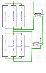
Why are you connecting the two buck converter's output and input (-) together? In my original schematic they weren't connected. The 12V supply is the same, connecting a wire between them is redundant since they are already connected together by the way the schematic works.
 
ningaman151 said:
www.recumbents.com said:
I did it for you -

bad.png

Now do you see it?

Why are you connecting the two buck converter's output and input (-) together? In my original schematic they weren't connected. The 12V supply is the same, connecting a wire between them is redundant since they are already connected together by the way the schematic works.

How about if you modify your own diagram to include the power supply so that it's complete? www.recumbents.com is attempting to remove your blind spot by showing how a single power supply would cause a short (completing the diagram). Either your bottom buck fries, your bottom row of battterys will explode, or your negative commons wires melt.
 
E-HP said:
How about if you modify your own diagram to include the power supply so that it's complete? www.recumbents.com is attempting to remove your blind spot by showing how a single power supply would cause a short (completing the diagram). Either your bottom buck fries, your bottom row of battterys will explode, or your negative commons wires melt.

What do you mean? The schematic is complete, 12V is a power connection that are all connected to each other. It is a staple in schematic capture software. I can include a connector for the power supply but that's about it, there's no point of putting a desktop power supply in the schematic and making it all messy.

I think I get why the less happens when the (-)s are shorted, but don't see why that is with only the 12Vs being the same power supply(as the schematic infers).
 
ningaman151 said:
E-HP said:
How about if you modify your own diagram to include the power supply so that it's complete? www.recumbents.com is attempting to remove your blind spot by showing how a single power supply would cause a short (completing the diagram). Either your bottom buck fries, your bottom row of battterys will explode, or your negative commons wires melt.

What do you mean? The schematic is complete, 12V is a power connection that are all connected to each other. It is a staple in schematic capture software. I can include a connector for the power supply but that's about it, there's no point of putting a desktop power supply in the schematic and making it all messy.

I think I get why the less happens when the (-)s are shorted, but don't see why that is with only the 12Vs being the same power supply(as the schematic infers).

The two lines www.recumbents.com added are the minimum number of lines to add to represent the single power supply (12v and common rails). By using the same common on the top half of your circuit as the bottom, since they are common coming from the single power supply, then you are directly shorting the bottom batteries and also shorting the output of the bottom buck. If you''re saying the "commons" exiting your power supply are isolated, that's a different story, and not what you described.
 
E-HP said:
The two lines www.recumbents.com added are the minimum number of lines to add to represent the single power supply (12v and common rails). By using the same common on the top half of your circuit as the bottom, since they are common coming from the single power supply, then you are directly shorting the bottom batteries and also shorting the output of the bottom buck. If you''re saying the "commons" exiting your power supply are isolated, that's a different story, and not what you described.
I'm sorry I think there is a misunderstanding. The ground of the desktop power supply is not connected to the buck converters, only the positive 12V is connected to the (+)s. I know that connecting the grounds shorts the batteries, that is obvious.
 
ningaman151 said:
E-HP said:
The two lines www.recumbents.com added are the minimum number of lines to add to represent the single power supply (12v and common rails). By using the same common on the top half of your circuit as the bottom, since they are common coming from the single power supply, then you are directly shorting the bottom batteries and also shorting the output of the bottom buck. If you''re saying the "commons" exiting your power supply are isolated, that's a different story, and not what you described.
I'm sorry I think there is a misunderstanding. The ground of the desktop power supply is not connected to the buck converters, only the positive 12V is connected to the (+)s. I know that connecting the grounds shorts the batteries, that is obvious.
Just to clarify what I'm reading. There are only two wires going from your power supply to your charging circuit, and both are +12V, one to each buck; is that your design? Stating another way, there are no common (-) wires from you supply to your circuit, yes?
 
E-HP said:
Just to clarify what I'm reading. There are only two wires going from your power supply to your charging circuit, and both are +12V, one to each buck; is that your design? Stating another way, there are no common (-) wires from you supply to your circuit, yes?

Yes, and I feel ridiculous for saying it :lol: . Let me get back to the drawing board and make a new schematic. :D
 
ningaman151 said:
E-HP said:
Just to clarify what I'm reading. There are only two wires going from your power supply to your charging circuit, and both are +12V, one to each buck; is that your design? Stating another way, there are no common (-) wires from you supply to your circuit, yes?

Yes, and I feel ridiculous for saying it :lol: . Let me get back to the drawing board and make a new schematic. :D

:thumb: Yes, painfully obvious when you see it, but hard to see if it's in your blind spot. But, just like with driving, once you aware of the possibility, you can modify your thought process to avoid them. With things that have a high level of risk, sometimes you need to start with an assumption that your could be wrong, before you can conclude that you're absolutely right.
 
Hi!

I haven't been able to test the continuity of the bunch converter's negative terminal, but I have a new idea.

What if I multiplex the output of the buck converter to each series stage on the battery? That way only one series battery pack will have power connect it to.

Does this look like a sound method?
 
as long as you move both positive and negative of the converter at the same time, first disconnecting boht of them from the previous connection before connecting either one to the next connection,called break before make, then yes, it can work.

however, you'd most likely need to use a mechanical relay system, which cna be quite large depending on the voltage and current involved, requireing at least one relay for each segment it is to be connected to.

alternately, a rotary switch wtih that many positions can be used,

to do it with solid state switches could also be done, but requires ensuring no leakage currents, etc.
 
amberwolf said:
as long as you move both positive and negative of the converter at the same time, first disconnecting boht of them from the previous connection before connecting either one to the next connection,called break before make, then yes, it can work.

however, you'd most likely need to use a mechanical relay system, which cna be quite large depending on the voltage and current involved, requireing at least one relay for each segment it is to be connected to.

alternately, a rotary switch wtih that many positions can be used,

to do it with solid state switches could also be done, but requires ensuring no leakage currents, etc.

I was thinking about using mosfets, which provide the same functionality as a relay (or I might be missing something)
 
ningaman151 said:
I was thinking about using mosfets, which provide the same functionality as a relay (or I might be missing something)
They don't exactly.

while fets *are* like switches in one direction, in the other direction they never turn off because they are essentially a diode, allowing current to flow thru them that way (and get hot).

so to prevent current flow in either direction you require two, back to back.

then you need gate drivers on each fet (which isn't really different from relay coil drivers except in potential complexity)

every fet system must eitehr be isolated from all other cell groups, ro it must be capable of handling the voltage difference from it to every other fet system it's connected to, so it all has to be rated for about the full voltage of the pack, if it's wired in a way that could allow a connection from the top of the pack to the bottom fet system input

because fets generally have much higher resistance than relay contacts do, the whole system may require heatsinking depending on the currents and resistances involved.

if a fet fails for whatever reason, it's likely to fail shorted, allowing current to flow between cell groups whenever another fet is turned on. that means losing charge on some cells, potentially draining them dead or even reversing them, flowing into others in addition to whatever current comes from the charger, and because of the voltage potential between the cell groups, could overcharge the cells receiving such current.


whether you use relays or fets, it's a complex system with a fair bit of wiring and/or circuitry and expense and size.

it's not impossible to do, and there are already threads about doing this kind of thing, if you look around the forum for multiplexing or switching single-cell chargers. i don't remember if anybody ever actually finished and tested such a system, but they've certainly designed them.
 
Eureka!

I think I have found it..

What if I use AC-DC converter to step down mains to around 12 or 5 volts for every series part of the battery and using a CC CV buck converter to use the stepped down and rectified voltage to charge the battery stage?

A video speaks louder than words:
[youtube]ks2LefmuNZY[/youtube]
 
amberwolf said:
ningaman151 said:
The esc has a cuttoff voltage of 42v. That would make packs of less than 16s unable to run with the full discharge range.
That depends on whether you want to kill the cells or not. ;)

Normally the lowest voltage you'd run the cells down to is around 3.0 to 3.2v for the common Li chemistries (other than LiTI and LiFePO4). There's not usually much capacity below that.

If you run down to the spec sheet minimum, especially at a high current, then you can easily overdischarge the cells, especially if they are not well-balanced. Each excursion below the limit damages the cells, so it's cumulative.

Additionally, the cells will unbalance more easily the lower you run them, making the problem more likely to happen again, each time you do it.


So, assumign a 3.0v cell-level lower limit, then the LVC for a 16s pack is 48v.

The LVC for a 14s pack is 42v.

The LVC for a 13s pack is 39v.

So for an LVC of 42v, on a controller listed as compatible with a 48v (13s) pack, it is using a 3.23v per cell lower limit, which is pretty safe.


A BMS, on the ohter hand, often uses a much lower per-cell LVC (as low as 2.8v), because it is a last-ditch line of defense against destroying a pack or starting a fire.

If you always run a pack down until the BMS LVC kicks in and shuts the pack off, it's really really hard on the pack, and it's useful lifespan will be much shorter than if a higher LVC is used.


YOu may "lose out" on 10% (up to 20%) of the total cell capacities...but they will probably last several times as many cycles.


So...specs for individual parts (like cells) aren't necessarily applicable when those parts are part of a system. The specs may have to be derated for actual usage scenarios.

Lots of research and reading still go go. ;)

How would I have it so that the electronics shut off when the cell voltage is below 3v?
 
Back
Top