If you're going to take the risk of putting oil in your motor, then be sure to add lots of surface area to the outside of the covers. Then it will truly accomplish a lot. More surface area means proportionately more heat dissipation at the same temp. If that new surface area is done in the form of blades, then it can also create a greater and more turbulent flow over the surface, which will also significantly increase heat dissipation at the same temp.
Without adding motor shell surface area the effect of adding oil is mostly just to delay the eventual heat up as GCinDC documented quite well. It helps increase cooling in intermittent operation but to be the effect is unimpressive. While it conducts heat more quickly to the covers, you're still stuck with the same surface area, which means to dissipate more heat the covers must be hotter. Guess what, that means your magnets must get hotter too.
Oil fill is definitely for moderate power builds unless you go the extra step and add something like double the surface area of the outside shell.
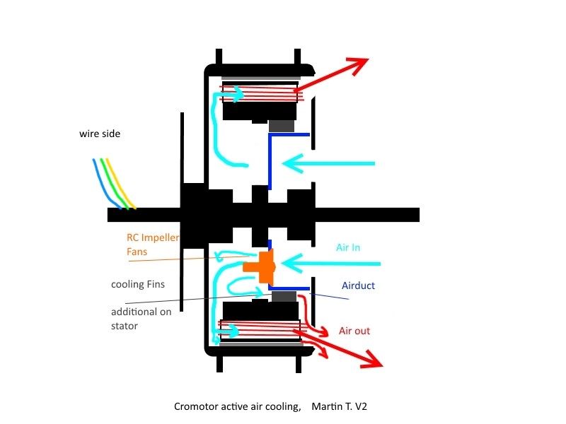
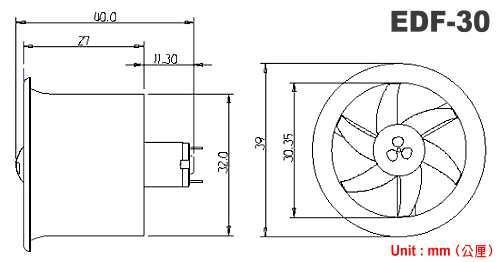
Fans sure, but people continue to use axial fans instead of radial fans (blowers), which will be far more effective because they're better able to create pressure in tight turbulent spaces where axial fan flow disintegrates. Plus with the blowers you direct the flow at the stator instead of the other side cover, so a double barrel benefit over axial fans. At low speed and forcing air flow while stopped is where interior fans pay the biggest dividends.
Holes in side covers help, but really only to the extent they let hot air leak out a bit more freely, especially when stopped, and maybe create a bit more turbulence at the windings. The most copied approach does very little compared to the risk of something getting into the motor with no way out. How many fans have you seen that consist of a relatively flat spinning plate with circular holes? Answer exactly NONE. I've tried hole shapes that I thought should create the right pressure differentials and a number of hole placements, and while all worked with each newer adaption working better with consideration always to minimize the chance of ingesting something problematic, NONE FLOWED MUCH AIR. Interior blades helped, but still without significant and meaningful air flow through the motor, it always remained possible to to overheat the motor at high power without getting abusive. I can overheat any motor in the right conditions and everyone should learn that limit for their own system and conditions.
Do yourselves a favor and do some research regardless of the cooling approach. With air cooling the numbers will quickly tell you that you need substantial fresh air flowing through the motor to carry meaningful heat out with it. I run my hubmotor at 27kw peak input, and while it's quite a bit more efficient than the common hubbies used around here, going from 16kw peak input with a stock motor and having to take heat generation into account while riding demanded serious cooling to add the additional 11kw via a 50% voltage increase and a 10% increase in current. Even riding at the same speeds as before required more cooling, because the higher voltage shifted the lower efficiency range of operation to higher rpm.
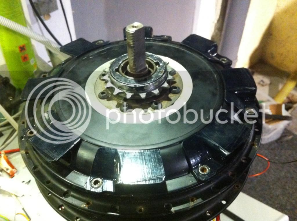
First I put about 100 narrow slots at the motor's perimeter on the exhaust side, and opened up the intake side as much as I dared. My hope was that these slots at the corner would act as small centrifugal blades. They did and it did flow enough air to feel with my hand very close and wheel off the ground, but we're talking about 10's of cfm not the hundreds needed. I was prepared for that result, and while I had the motor apart I drilled and threaded bolt holes near 6 extra long slots I cut in the shell, so I could experiment with exterior blades that also extended inward to also get the interior blade benefits I've obtained before.
The end result speaks for itself. Me and my bike together weigh about 190kg. The shell of my motor has less surface area than most DD hubmotors used here, yet despite running higher power through a hubmotor than anyone around, and pushing a much heavier load than most, I rarely even turn my temp sensor and alarm on. When I do it's only out of curiosity. A friend has a dense smoke machine for finding air system leaks in cars, and it showed the motor both sucking significant air into the motor, as well as a surprising by-product of sucking a lot of air across the motor through the rim holes. That meant it was providing extra cooling of the magnet backing rim from the outside with extra air flow from left to right. I didn't video it primarily because when I moved the hose further than about 1cm from the intake side, the turbulence of the spinning tire made the smoke mix with the air too much to really see it being sucked in, but the generally smoky air on the other side told me it was still drawing in. When I ventilate my next one I'll make a collar using a large diameter of cardboard to move the intake well away from the wheel turbulence and really show how strong the air flow is.
The changes I make will be to make only as many exhaust holes in the motor as I have blades, probably 8 next time. I'll cut the slots to secure the blades at an angle instead of straight radial, so the blade protects the hole from debris (I've never gotten any debris in any of my ventilated motors, and I go small with holes and/or slots to keep it that way). To counter the reduce flow effect of the angled blades, I'll put a forward curve near the blade end to make the tangent at the tip parallel with a straight radial. This will help the blades fling more air away at the blade tips, which is how centrifugal fans work...ie flinging air away from the blade edge creating low pressure behind the blade.
Here's a picture of one of the blades made from rust resistant 1"x1" thin angle steel used in home roofing. I cut them simply with tin snips. The silver part is outside of the motor. The blade edge is at the bottom in the pic. The green is the thickness of the motor shell and the black and yellow protrude inside almost touching the motor end windings.
View attachment 1
Here's what they look like mounted on the motor. Note that the angle steel give it good rigidity, and the side facing portion at the perimeter helps prevent air from rushing in to fill the low pressure area behind the blade. I did bend those sides slightly away from the motor thinking that would open up more of the slot behind the blade as well as push air away from that side.
I apologize for so little documentation, but this started as a test, and it's worked so well I haven't done anything further. The best examples of how well it works are:
1. With the motor already at operating temperature of 50-60°C, I did a high speed climb with the first few km averaging 5% grade, and the last 2.5km a solid continuous 20% very curvy and accelerating hard from very slow in each curve to up to above 80kph when there was enough straight to allow it. It was my first time up the road so I was extremely slow in each curve. The stator only got to 105°C, the hottest I've ever had it.
2. On a 15km ride mostly highway including one 2km 7% climb and back down the other side to a long slight grade into a headwind ending at a 200m net increase in grade, and speeds never below 90kpm after entering the highway and showing off for cars a couple of times up to about 120kph, stator temp very gradually climbed to 68°C when I parked. I haven't worried about motor temps since.
If I used a hubmotor for an offroad bike sure I'd use fans in the motor due to the low speeds, but they'd definitely be radial fans, not axial fans like everyone mistakenly uses. For the motor to act as a centrifugal fan itself, the higher the rpm the better. However, an offroad bike for me would see Pacific beach use too, so I'd go mid-drive using similar ventilation, but put a shell over the motor to provide a protected intake and an exhaust duct common of centrifugal blowers all in an effort to keep salt and sand out. With a hubmotor I'd get someone to build me a Lebowski controller or two, so I could forget about the halls, and epoxy up everything very well, add lots of outside surface area by welding AL blades to the covers, and fill it to an inch or two below the axle with ATF.
One more word about blades. People often mention exterior blades in the form of scoops or whatever. They're all just axial blades, and a waste of time. It's totally impractical to get sufficient blade size for the operating rpm, and even if you did the intake side would deflect sand, dust, and debris directly at the intake side of your motor. OTOH at the motor diameter and rpms we operate a well designed centrifugal fan can create enough pressure to move a lot of air. I can feel the exhaust side of mine throw off more air than the intake even from a couple of feet away from the wheel when spinning it up no load, so I know I moving air. While it's nowhere close to optimized, I quit because it works well enough and I can barely detect any increase in no-load current, so even at high speed the power cost has to be less than the reduced resistance of a cooler motor.
I'll do a good thread with video and lots of pics someday, but I'm really slow with that kind of stuff.
John
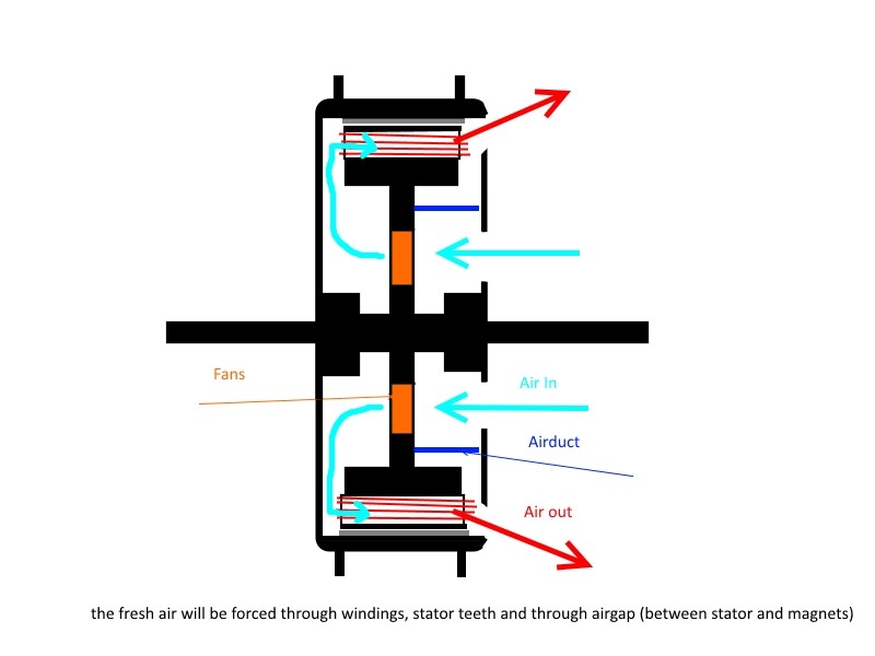
PS- Please ignore all of my posts related to air cooling prior to 2013 when I implemented this exterior blade approach. Much of it was accurate, especially the use of interior blades and putting exhaust holes at the extreme perimeter of the motor along with one sided intake and exhaust to get air flow through the magnetic gap where it is badly needed. The bladed approach is so each and effective and only needs a fairly small number of exhaust holes to function far better than anything short of putting a noisy high power blower pushing massive air at and through the motor like Toolman2 did. He shared even less detail than I have other than to measure the effect of 1000W reduced resistance in the windings of his extremely stress RC motor.