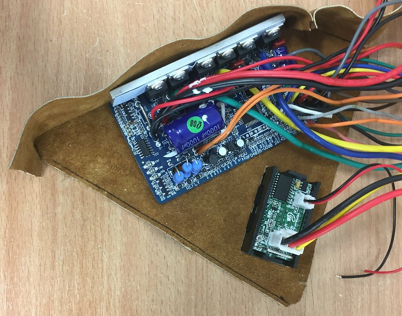
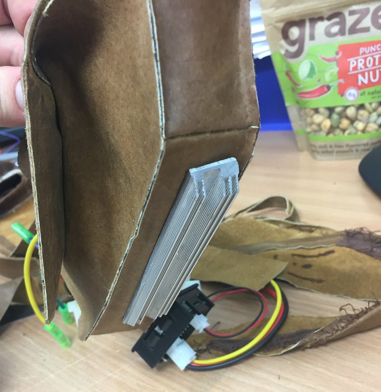
@mrdude_1 I like your thinking. I'm going to wait and see if i need the room for the connectors. if it's not full sardines I may make a smaller one.
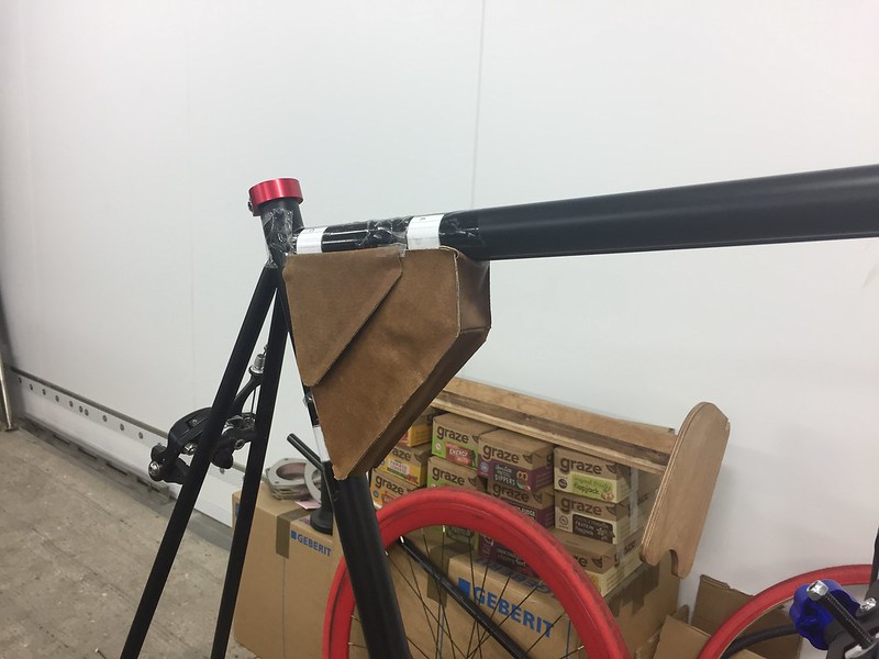
@d8veh the ally case makes the footprint so much larger in all directions, i want to keep the bag as small as possible. The PAS will be the next step, this is a way to get the project going, i doubt this will be my first and last eBike build so I'm trying to do it on a budget, fail fast and learn a lot. I'm most interested in whether it will work how I planned in my first post, whether i can get the top speed from pedalling and gearing the drivetrain so, and using the motor to get me off the line at the 20 or so traffic lights on my commute. PAS doesn't work very well when you first start i've heard? If i was trying to take off up a hill i could go nowhere.
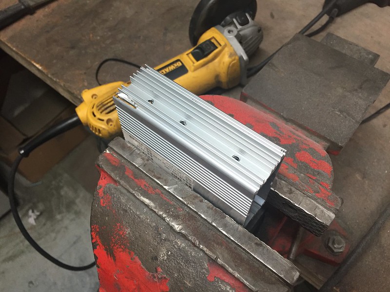
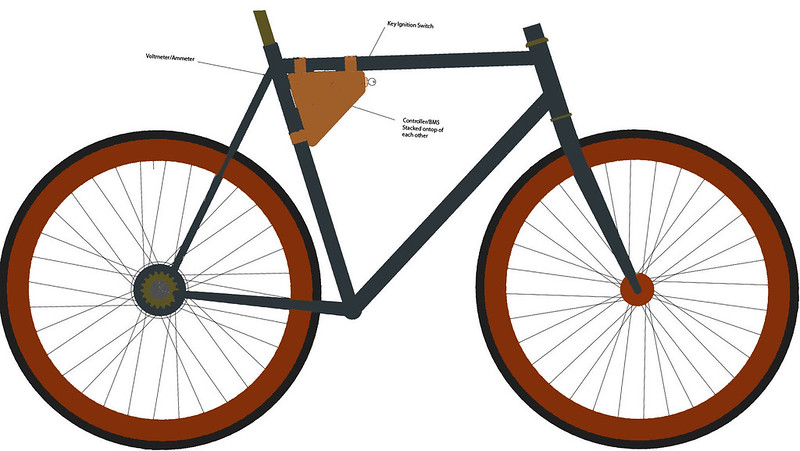
Motor Modifications
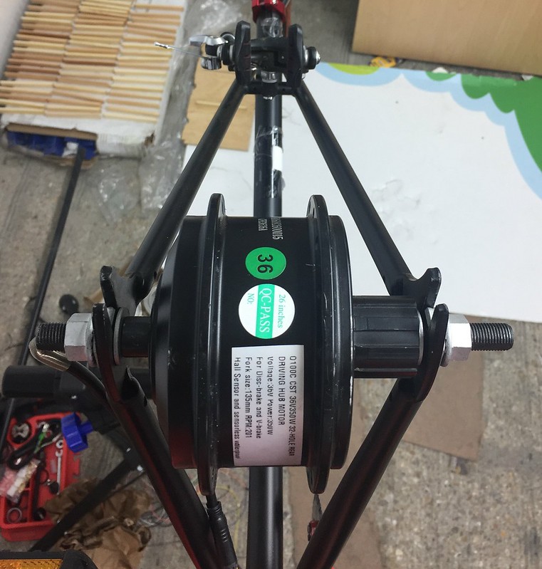
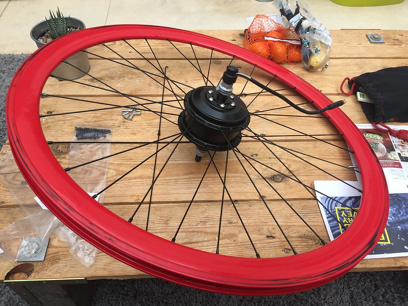
After making the mistake with the first motor I ordered of getting a 36 not 32 spoke hub I couldn't find a hub motor the right width, so I took a punt and got a 135mm wide motor hoping I could modify it to fit. It arrived today! I'm happy I made the swap, it's about half the weight of the 8fun one I started with. Apparently the same specs...
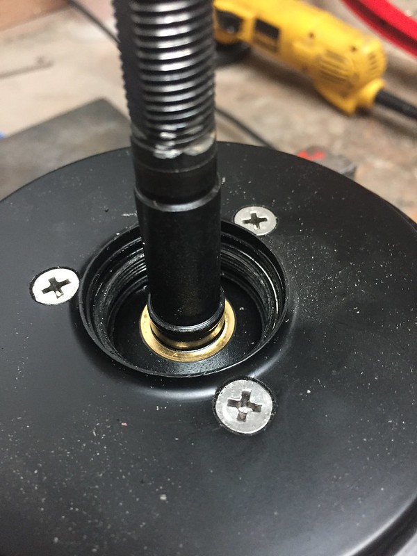
It came with a free hub to fit a cassette, I wasn't sure what fitting out be underneath, hoping it would be a male thread I could put the single gear freewheel that came with the bike on. Instead there was a female thread which I couldn't find any information on, i'm guessing these components are unique to hub motors? Has anyone had any experience with these?
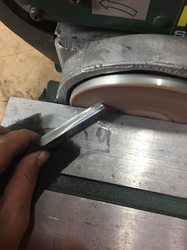
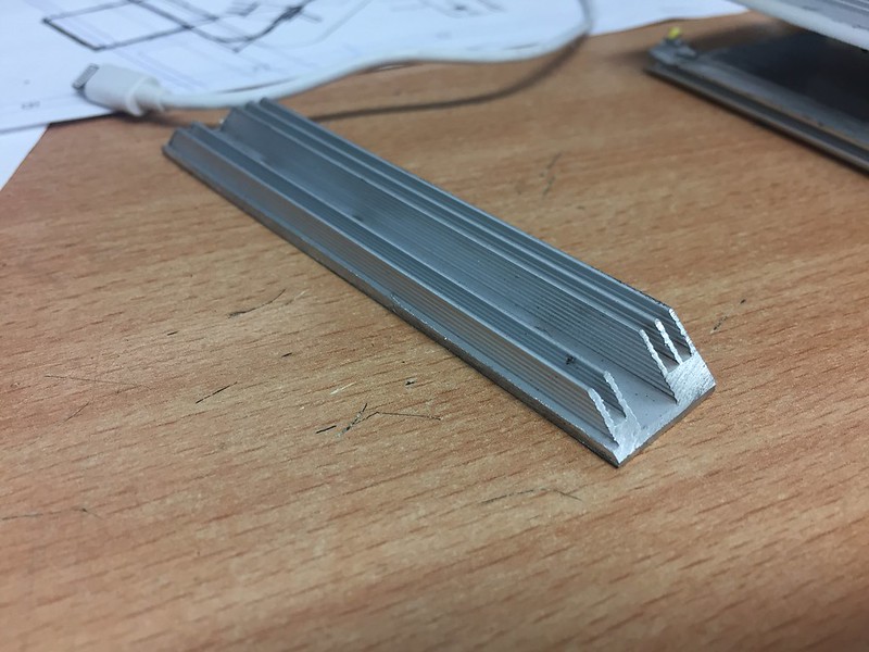
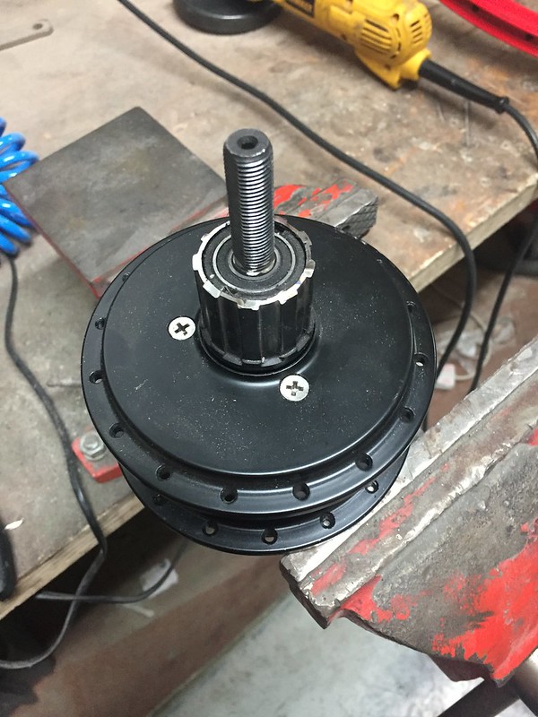
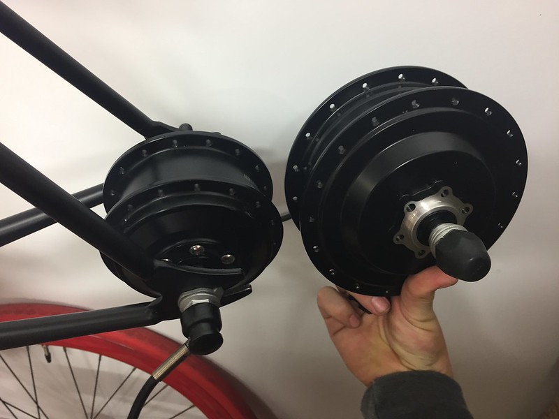
inspecting further I saw that the freewheel had two bearings that positioned on the shaft and secured it to the motor, which had to stay. So i cut it down as much as i could keeping this in tact.
I then just had to file down the shaft a little to fit in the frame properly, i wasn't too worried about tolerances on this cut because the torque washers would still be seated on the original flat reducing any chance of movement under load.
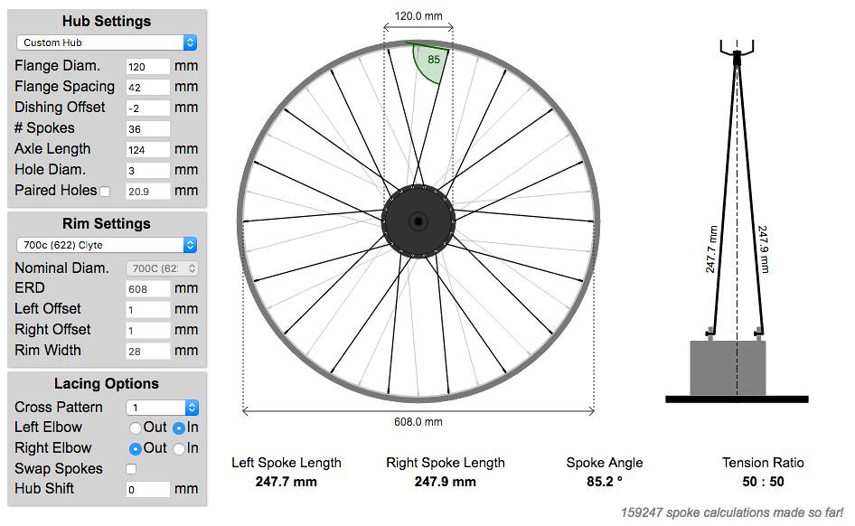
This all worked out pretty well for centring the hub in the frame, i did a rough measure and found the centreline of the motor hub only to be 2mm offset from the frame centreline.
I checked this on the webpage i mentioned earlier for calculating spoke lengths on hub motors.
http://www.ebikes.ca/tools/spoke-calc.html
Ta Dah! There is a bit of tolerance in my measurements, but it's come out at 50:50 tension. I don't know if there are any issues caused by putting the spokes right on the right hand side of the hub flanges.
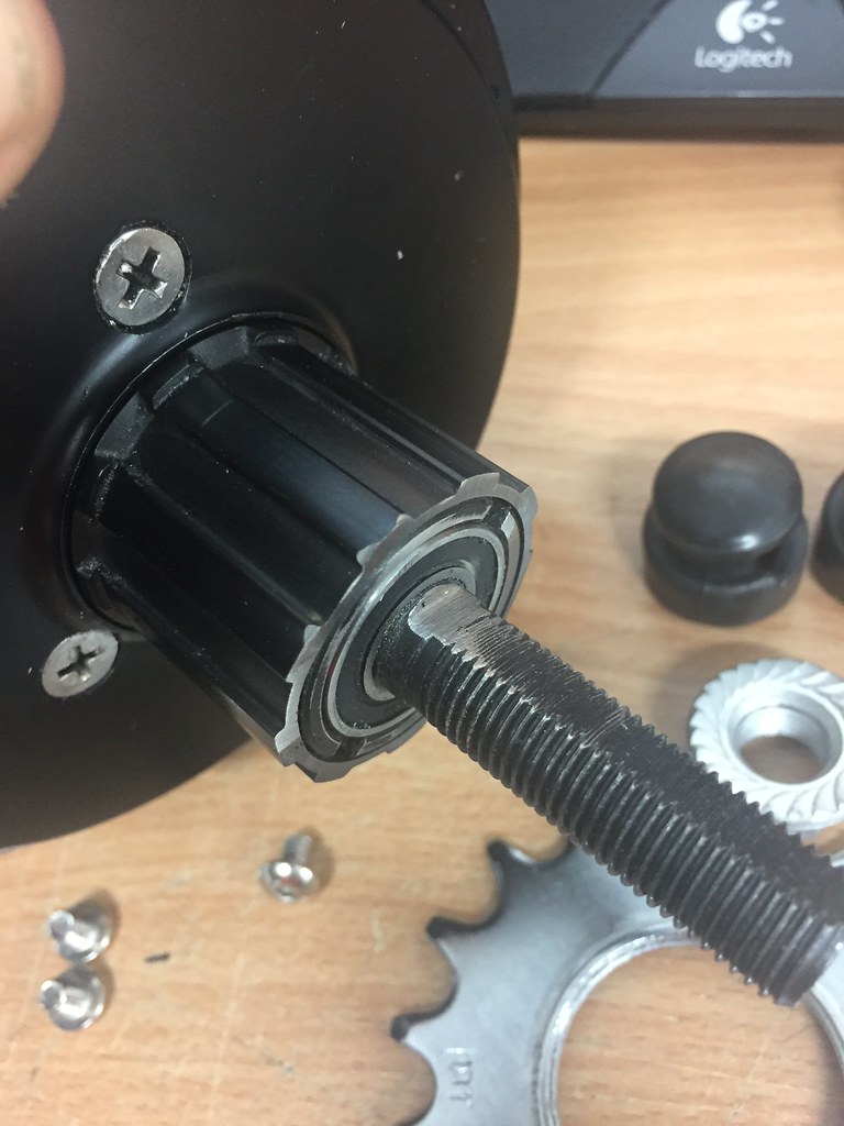
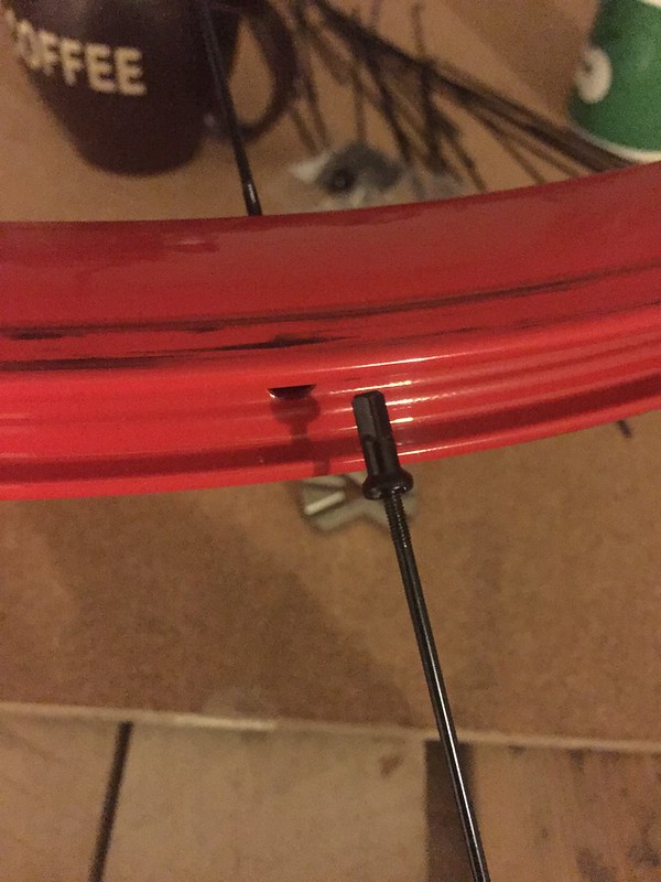
I cut off the thread on the freewheel which usually holds the cassette on, my plan is to file a groove on the freewheel which i can put a circlip on. I can then position a single sprocket with spacers either side to get the chain line right, like a lot of single gear conversions I've seen.
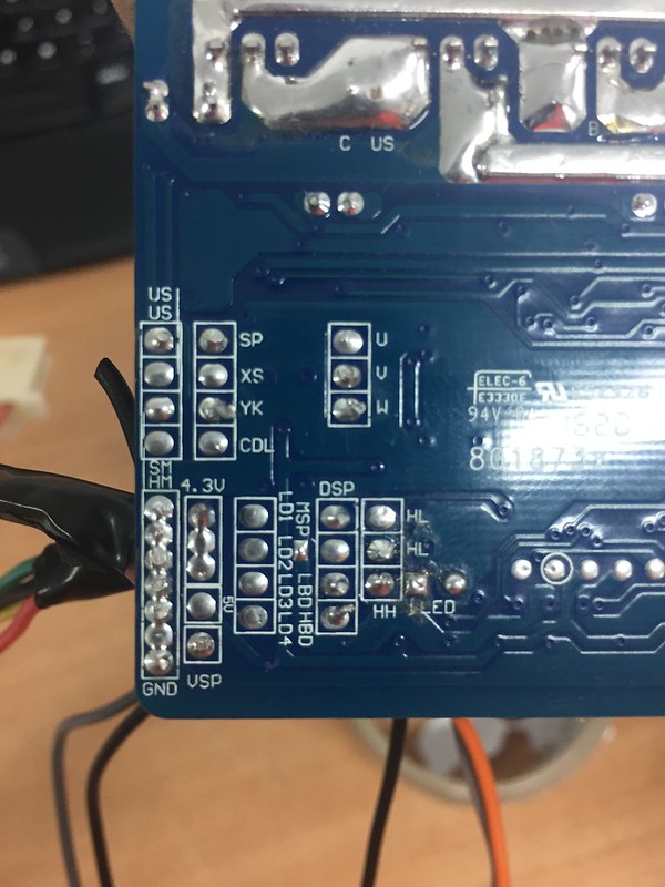
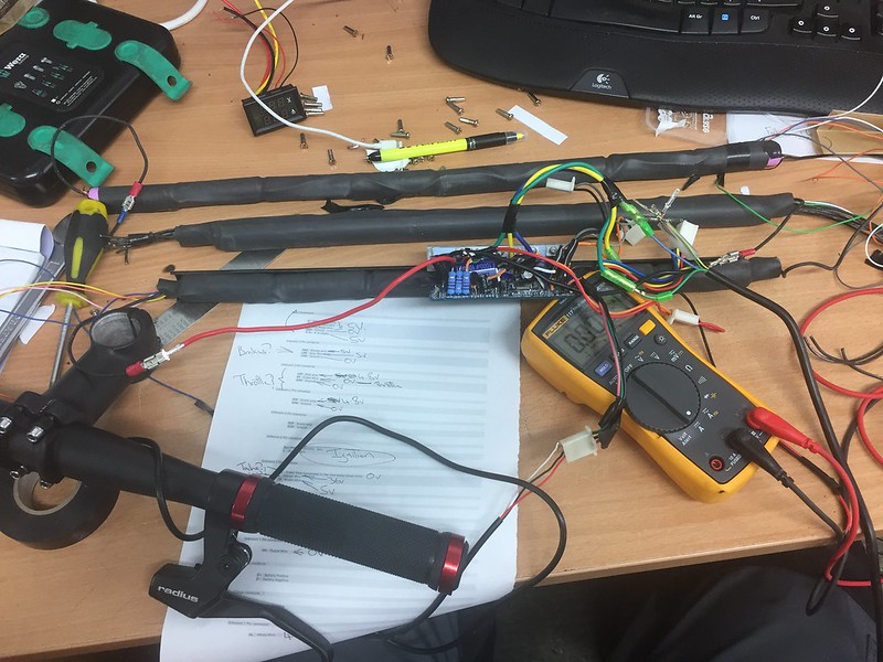
I think I've now got everything I need to give the whole system a bench test, so that will be my next step early next week.