CroBorg Super Commuter

My instinct is that a soft plastic/rubber/fiber washer might just provide a bit of compliance around the hole that could help reduce cracking over time, or rattles, noise, or whatever else. I would be inclined to use a larger diameter metal washer under the screw head, then a compliant washer under that--- spread the load and pressure out as effectively as possible. Depending on the type of plastic used for the canopy this may or may not be that important- can't really hurt though.
 
Alan B said:
Still need to glue the cracked cover and paint them. Probably need to shave them a bit for better fit before painting. The goal there is to reduce the stress a bit so they touch the tubes at the same time rather than in some spots first and place stress on the material.
Another strategy here is not to stress your time and craft with a fussy accurate fit, but simply to cover up the hard parts (an old carpenter once taught me the real reason for molding :) )

You might get some split rubber molding about 3/8-1/2 inch high and just slip in on the edge of the panels. Done! This might also let you pick up a very small bit of extra width. Once the panel is screwed down, just slide the trim to touch the frame - goop in place in few spots if you wish.

A quick search on eBay turned this up, but there are many products available from normal suppliers including less squishy non-neoprene moldings (eBay "Rubber Edge Trim 1/16").
 
Good suggestion, but this would have to be done before the holes were drilled in the side panels, it would change their location. :)

I won't make the fit too precise, I'm not patient enough for that. :)

Rivet Nut Installation DIY style

I did not buy a special tool for this, they are available from $30 to $600 but the space available for the tool is restricted and it is not easy to tell which tool will fit. So I made a rivet nut tool, if you can call it that.

6-32 by 3/4 socket head screws
#6 washers, 2
#6 nuts
1/2 by 1/8 by 2" aluminum scrap

Drill a hole in the center of the aluminum strip to just clear the #6 socket screw

Oil the screw and spin the nut all the way on, then the two washers, then insert through the hole in the aluminum

Spin on a rivet nut with the flange against the aluminum

Insert into mounting hole on the Borg frame from the outside (in direction screw will mount):

DSC_9747.JPG


Hold the rivet nut in place flush against the mounting hole using the hex wrench in the cap screw.

Turn the nut clockwise and expand the rivet nut just enough to be snug plus a little more.

DSC_9748.JPG


DSC_9753.JPG


DSC_9755.JPG


Relubricate the screw every few rivet nuts and replace nut and/or screw if they become damaged.
 
Battery Install

Installing Coroplast between the frame and the battery to protect battery from the frame. Using 3M filament type shipping tape.

DSC_9749.JPG


Installing 12 each 6S 5 amp hour Lipo batteries.

DSC_9751.JPG


Now a layer of Coroplast is added on top of the batteries to protect them from cables and modules that will be located there.

DSC_9756.JPG


Next step will be the wiring harness. :)
 
Oh my, so soon, by Port Dover day I hope!
Have 99% of the bike done, but just need to do all those little connectors.... ugh, soldering iron broke, so I have to use a crappy tire one for now. :roll:
But soon! Sorry to drop a diary in you build thread, but hey! She looks sick Alan!
Beauty. These bikes are pure awesome.
I think since a bunch of people now want me to build them these, I will create a small business of sorts.

First though is that spacer for the schlumpf, I have epic all of the sudden access to welding and lathe/mill equipments so I am set for custom fab, who knew my brother knew so many people!

Then the cell holders which shall be a brease, then she rolls!
Glad to be a Borgzilla brother!

Cheers
SRam
Alan B said:
How soon Sam?

Progress Update

I'll be getting washers tomorrow so today I focused on details electrical. Installed a lot of connectors, hooked up 10S Zippy batteries, and clamped the motor in a Black and Decker Workmate. No Joy. Went to 15S of Zippy 8AH packs and... it lives! The controller LVC probably kicked in.

Also, don't use the Workmate to clamp the motor for testing. It might work with a light bicycle wheel, but this heavy wheel was too much and the axle spun 90 degrees. I knew it was sketchy and even though I was trying to be careful and gentle it still spun 90 degrees. No harm done, but be careful.

The wiring used for phase and hall sensors was color to color on this Lyen 24 FET controller. Nice. :)
 
hi guys n gals,
sorry to interupt the thread but is there a price on the croborg frame?
maybe some estimate prices on parts. eg. frame, cromotor and any other part relevant to the frame?
looks very interesting and could possibly purchase this in the future.

cheerios

bruce
 
saiyan send a pm to Accountant he is the best person to tell you the full package price.
 
More on Batteries

I didn't take a new photo, but I adjusted the battery mounting of the upper pack to put a slight space between the fore and aft packs to facilitate wire routing up through the packs. I did that after a trial fit of the side cover showing how little space there is alongside within the cover. I'm trying to avoid having pressure on the side cover that will likely break out the mounting holes.

I'm working on a wiring harness plan. Going to use the hydraulic crimper on this one. :)
 
Hey Alan-

FWIW- I think my take-away from ruining a cell in my pack from physical movement/vibration was essentially that the cells should either be absolutely rigidly attached to the adjacent material (tough carpet tape- maybe. compression clamping system- yes) OR the cells should be insulated from the adjacent material with compliant foam. In my application I have put foam in between the bottoms of the cells and the adjacent material (corplast). In my analysis of my incident I determined that the corplast itself provided little to no cushioning. It was not even slightly compressed from the forces that completely ruined the cell that stood slightly proud from the rest of the pack.

I think the HK packs are more tough (with the shrink-wrap, etc) than the bare pouches. Your setup may well be fine. I think it would help to eliminate the risk of cell damage to put a thin layer of foam (a mousepad, or equivalent) between the cells and the corplast (corplast functioning a bit as a load spreader).

-H
 
Good points, Henry,

I'm not thinking of cushioning with the corrugated plastic, but as a smooth material for a force spreader and puncture preventer. It also is a great surface for taping against and to, so it makes a good mounting material.

Interesting suggestion of adding a foam layer. I have some foam interlocking floor pads that would work, but it would take some space. There is probably enough room. Now is the time to do it, though I'm tiring of removing and reinstalling the batteries, have done it about four times now. :)
 
Hydraulic Crimping

This afternoon I spent some quality time with the Hydraulic Crimper. These copper crimp rings are excellent and inexpensive, but the two sizes available have capacity for 2-3 #12's for the small ring, and 3-5 #12's for the larger ring. For a 4P configuration, with per bank charging I need to join about 9-10 #12's at each joint. That's a bit much to handle, so I am layering it into two levels. Here are the 12 battery plugs combined into six pairs before the heatshrink went on:

DSC_9762.JPG


With this design the main current is carried by pairs of 12 gauge wire. According to wire charts a 12 gauge wire in a chassis can handle up to 41 amps, whereas the NEC calls for 20 amps maximum in 12 gauge house wire. According to another chart, 12 gauge single conductor TW wire in open air at 30 amps reaches a temperature of about 140F.

The Cromotor is rated for 3kw which at 72 volts is about 40 amps which is where I plan to set the controller in normal use (and use the three speed switch to lower it from there). So a pair of #12's is the minimum I would use. The controller has a #10 input wire which is slightly less copper than a pair of #12's. So it matches the pair of #12's fairly well. Pairing wires reduces the gauge by three, so a pair of #12's is a #9 and four #12's is a #6.

For my charging lines to each 6S4P bank I am using #14. This wire is conservatively rated at 15 amps by the NEC, and charts show 25 amps at 140F and 32 amps in chassis use. This should be adequate for charging at up to 15 or perhaps 20 amps.
 
Afternoon Ride

Just returned from a nice afternoon test ride. Over 30 miles, about 15 amp hours (out of 20) at 18S 70V. I LIKE 18S on the Cromotor. :)

I tried 12S, 15S, 18S and 22S on my Cromotor. I LIKE 18S. Great compromise. :)

Maybe that's why they rated it 3000W at 72V. Pretty good spot to operate it.

I did more than half of the three bears loop, plus a side trip, and then turned around and did it again. Lots of climbing, lots of pedaling on a beautiful warm California afternoon. :)

I never did a top speed check, but it will cruise easily at 30 mph, and downhill pursuit at 40 mph is no problem :mrgreen: . The Magura throttle is very controllable when riding at a few mph right on up to whatever is max. No scary control of acceleration, though it can come in suddenly if you are moving along and roll up the throttle to find out where it kicks in. This is with the 12 FET controller, the 24 FET controller definitely has more grunt at the lower speeds where its higher phase current settings work their magic. Also stuff that heats the 12 FET doesn't heat the 24 FET much if at all.
 
I've Got it Covered

IMG_20120707_141424.jpg


(Not a bad pic for a Camera Phone...)

This is how it looks right now with the factory white side panels. Location is San Pablo Dam Road, San Pablo Reservoir in the background. Part of my work commute and the Three Bears Loop ride.

It feels nice with the cool white panels so you can 'grab' the bike with your legs. It is about 4.5 inches wide so not an impediment to pedaling, just there when you want to touch it.
 
Battery Protection System

Installed the Methods HVC LVC Parallelling boards. Installed balance leads from these boards paired to the per bank charging Anderson Powerpoles. So now I can charge this beast with a 6S balancing charger, one bank at a time, at up to 20 amps. :)

Eventually the low and high voltage cutoff features will be utilized as well, via my own very special power, bulk charging and throttle management board. The board has been on the bike for awhile doing the Magura throttle spanning. The rest of the circuits have not been tested yet. May have to do that soon. :)
 
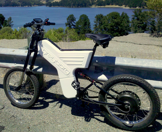
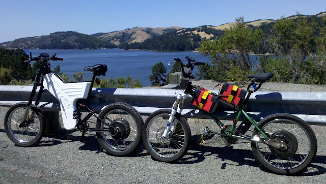
San Pablo Reservoir on a Sunny Afternoon

IMG_20120708_145522.jpg


Joined by acuteaero this time for a nice test ride. We did the Three Bears Loop. I hope he wasn't too bored. Nothing too exciting, though the weather was nice and there were a few cyclists out. One passed us going 50 mph on the Big Bear downhill. :shock: But we blew by him on the uphill. :)

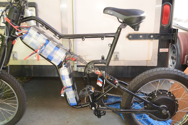
Charged last night and again now via the balancing leads with the Hyperion 1420i. At the moment I'm charging each 6S bank individually, later I may do 12S and 6S chunks for two hookups, or even use a second charger for the 6S part and charge them concurrently. :)

On the first paralleled charge cycle the third bank of 6S4P took forever to balance. These batteries were all individually charged and checked, but some were from an older batch and had sat around for weeks at full charge. The other batteries took a couple of hours to charge at the low initial rate, but the third block was balancing for another couple of hours when I finally interrupted it because it was time to go. It was at 97 percent, no not much to go, but it was going very slowly. On the charge after today's ride all three banks took between 80 and 90 minutes, so the balance seems to be sorted out.

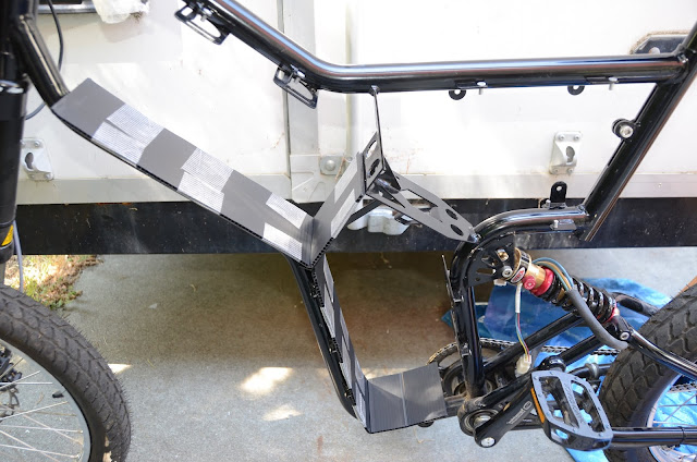
It is convenient to have one small lower cover removed for easy access to charging connectors and getting the motor cabling out. If the lower right panel is left off this would also allow running a larger chainring which is appealing. I might consider making my own custom lower right hand cover that would facilitate a larger chainring and the charging connections.

This trip consumed about 12.1 amp hours, but the CA indicated 13.5. Comparing the charging amp hours to the CA it seems the shunt is about 1.5 milli ohms rather than the 1.7 I was using.

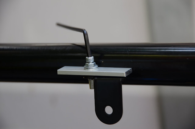
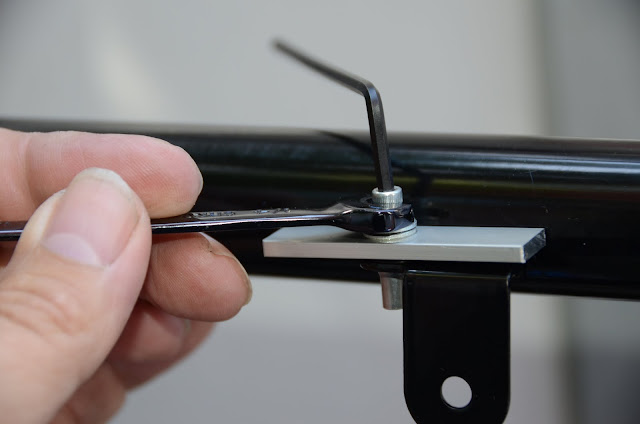
I also checked today to see if a metric allen wrench would work on the 6-32 panhead cap screws holding the covers on, and the 2mm fits perfectly. :)

I was looking for an old bike multi-tool that I purchased some years ago and didn't use. Found it, and it turns out to be a Topeak Alien. Amazing collection of tools in one compact package.

Ordered a seatpost mount Topeak MTX rack type V. From what I read these racks can break from too much weight and abuse (like carrying batteries and doing rough riding), but with the gentle riding and light trunk weight I need for commuting hopefully this won't be a problem. I'm also looking at ways of strengthening the rack.

Installed the mirrycle mirror today and really like it on this bike. There is no vibration so I can see a long way back. This is much better than my other bikes with the same mirror, the dual suspension (and weight?) seems to really make a difference in the stability.

It was interesting to compare the Cromotor to the HS3540 in acuteaero's BMX. The Kv of the HS is rated at 10.225, and the Cromotor 9.5. We were both running 18S packs, though the Borg's Turnigy voltage is slighly higher than the BMX's Kokams. The 2.5" moped tire was on the HS, and a 3.0" moped tire which is slightly larger diameter was on the Cromotor. Both the voltage and the tire size were in the direction to reduce the Kv difference of the motors. So the 18S Cromotor in the 17" moped tire tops out just under 40 mph, and the HS just over 40 mph. Of course we kept our speed at a legal 20mph except for some downhill sections. :mrgreen:
 
Charging the Borg

I threaded 6S bank charging wires and JST-XH balance extension leads down to the crank area where the missing panel allows good access. These were labelled and tie wrapped together to minimize the potential for errors.

The procedure is to use a 6S balancing charger with PowerPoles and JST-XH leads. Plug in the PowerPoles first, then the balance leads. I am using the Hyperion 1420i which is good for up to 20 amps at 6S, though so far I've only set it for 15 amps. It takes less than 90 minutes to put back 12 amp hours into one bank, which I must repeat 3 times for a full charge cycle.

It is really good to balance charge every cycle for awhile until the batteries are proven. Then bulk charging is an option.

Another interesting option is to use a pair of balancing chargers to balance charge the whole battery at once. For example, a Cellpro 10S can balance charge 6S at 10 amps which is 252 watts. The Hyperion 1420i can balance charge 12S at 10 amps which is 504 watts. So if we use both these chargers together we can balance charge the entire 18S pack at 10 amps. This requires two AC supplies since the chargers are operating at different potentials.
 
...crimper...gimmie... scared imma get cancer from all this soldering... silver bearing is lead free but man this flux puts off some fumes... drives my wife insane...
 
Safety Day

A couple of weeks ago we had a "Traffic Safety Day" at work. Bicycle safety was a major part of the theme. Our site is pretty steep, so bicycles reach high speeds at times. The streets are narrow and congested, and the speed limits are low with many stop signs. There have been some significant accidents, including one years ago where a pedestrian was killed by a cyclist (actually offsite but near the worksite).

I brought in the Borg for the occasion and displayed it to many interested folks. There is a spirit of the electric revolution at this workplace - it is a National Lab where engineers and scientists work on many things including materials science, lithium battery technology, solar panel technology, and many employees here have built electric cars or bikes, starting a long time ago. The Prius and Leaf are very popular, and there are a few Volts as well. Not to mention a couple of 125 KV feeds, but that is another story. There are not too many ebikes, perhaps because the usual fare doesn't work on these gradients (some over 10%). My old 49cc Motobecane crawled up this hill at 9 mph when I started work here, and was soon replaced by 125cc then 500cc). There are a lot of Gem NEVs but they don't go too fast up the hills, which is generally okay for the short trips and low speed limits anyway.

Quite a few folks took photos of the bike, one sent me a couple of shots.

I think the Borg looks a lot better with the covers on, but here it was a couple weeks ago:

BikeTuneUp_AlanBiocca.jpg


At that point I was running the 12FET controller, and in the cardboard box are two battery packs - a 15S 8AH and a 12S 8AH.
 
At 22S climbing big hills at medium speed (15-20 mph) the 12 FET got fairly warm when in open air. With less load it runs cold.

I expect at 18S that it doesn't get as warm, but with the covers on it might get even warmer, and I can't tell because I can't reach it. Eventually I will put some ventilation in, and perhaps a temperature gauge. With the 12 FET I don't think the motor will get warm so watching controller temperature is more important. If you were to go really slow on steep trails then perhaps the motor would get warm too. Then you might want to monitor both motor and controller temperature.
 
Look sweet, Regard the HS vs CroMotor, I rode Eric's green machine MTB with HS3540 and this thing eat battery energy so FAST!

I forgot name the guy rode his xtracycle and I always full WOT non stop chasing him as he was lead guide in SF in past. Eric had to replace the 48v 10Ah battery pack twice. I cant remember but it was near 40wh/hr. I believe CroMotor is slow winding should much less wh/hr than HS35.

Keep it up, I love hear your stories. :lol:
 
Back
Top