Crystalyte 408 hub motor repair (and controller issues)

ralphius

1 mW
Joined
Mar 3, 2019
Messages
15
My Crystalyte 408 rear hub motor has stopped working after some recent rain. I've diagnosed that the windings and connectors are ok, but the hall sensors are not switching anymore. I've never had this motor apart before and I bought it second hand. I'm guessing it's about 10 years old and has been on at least three different bicycles.

So, how do I get the damn thing apart? It looked easy yesterday, just undo the 6 bolts with an allen key. I've also managed to wiggle out the white (Nylon?) piece that the wires go through.

I had a brainwave to use a bearing puller between the disc brake and the axle, see photo below:
clyte_408_1.jpg


Unfortunately this has simply bent the arms of my disk brake where I had the bearing puller hooked in :-(

Can I check I'm doing the right thing here? Any suggestions of what I'm doing wrong?
 
I'd undo the bolts on *both* covers.

Then *CAREFULLY* run a razor blade between the cover and the rotor (spoke flange), ensuring you do NOT push it farther in than the depth of the flat edge of the cover. (it should not be possible to do so due to the cover lip inside, but if you did somehow do it, it could cut into the windings that are just inside this). YOu also don't want to break the blade and send fragments flying into your face, or slip and cut yourself open.

This breaks any sealant used to glue the covers down.

Then take the wheel to a nice thick concrete area, like a sidewalk curb, and place a block of wood there. Harder wood is better, but whatever you've got that's like a 2x4, etc. Then, firmly holding the tire, vertically whack the axle end on the wood block. (the block will prevent damaging the end of the axle). This should finish breaking any sealants, and push the opposing side's cover upward a bit. Sometimes it snaps back down, so it might nto be visible but you can usually hear that it did this.

It is possible to break one of the covers in this process...but I've only seen that posted about once, on a rusted-solid scooter hubmotor, a long time ago.


Note that if it has wires that come out of one axle end, you do not want to use *that* end to whack on the wood, or you may cut thru wires in the process. :/

Once you do that, you can then use that puller and put it's center on the axle end you just whacked on the wood. Put it's jaws on teh spoke flange, and then slowly and carefully turn it's handle, observing that the opposing cover is rising off the rotor (spoke flange). If it is not, STOP, or you can break the spoke flange you're pulling on with the jaws; this can happen very suddenly.


Alternately, you can instead stand on the rim (if you can balance the wheel on the axle tip ;) ) and use your weight to force the rotor off teh stator, which would also push the cover off with it.


Many motors ahve the hall sensors actually installed on the side opposite where the wires go in, so if you need access to them, and aren't sure which they're on, try remving the nonwire-side cover first. You might ahve to take both off.


Some hubmotor disassembly threads talk about using paint scrapers or screwdrivers...but these have a high risk of slipping and destroying windings. So I don't recommend them. :(
 
Many thanks for that advice, I've now managed to pull the stator, axle and brake\wires side cover assembly out of the wheel as one unit. See photos:
View attachment 1


Unfortunately, the break in the hall sensor wire seems to be somewhere between the side I can get at in the photo above and where the wires exit on the disk brake side. I've still got to get that other cover off somehow. It seems to be seized solid round outside of the axle bearing.
 
ralphius said:
See photos:
Can't see the images (probably because I don't have a login for that forum). If you attach them to your post directly, here on ES, then anyone that cna see the post can see the images.

Unfortunately, the break in the hall sensor wire seems to be somewhere between the side I can get at in the photo above and where the wires exit on the disk brake side. I've still got to get that other cover off somehow. It seems to be seized solid round outside of the axle bearing.
If the bearing itself has corroded to the axle, you might free it by using a bit of PB Blaster's penetrating catalyst first, let it sit for a while (maybe at least overnight), and then a bit of their lubricant. (tehy sell a "kit" with a can of each). It doesn't always work...and I have had to let stuff sit for weeks (months in one case, retreating periodically) that was really rusted badly...but sometimes it works a miracle. :)

If you have a wrench socket or other tube that will fit over the axle and sit against hte face of the inner bearing race (not the side of the bearing section itself, the seal), you can use the wood block / hammer to tap directly against hte bearing itself, which is much better than pulling or tapping on the cover (which can damage the bearing). Otherwise:

Then try pulling the cover *gently* with the 3jaw puller. If it doesn't move with the first turn of the handle, be careful of pushing it so you don't break it.

You can try tapping the center of the puller's handle with a rubber mallet, or a hammer on a wood block betwen the hammer and the puller, first gently and then firmer, until it breaks loose the stuck joint.

Or take the disc off (assuming it's bolts aren't rusted to the cover), and then use the wood block/hammer to tap the brake moutning ring around hte bearing, just to cause the vibrations to break up some of the corrosion.
 
Turns out all this fighting to get the hub motor apart was not needed. I made an assumption about how hall sensors work that was incorrect, turns out they are working after all, it's my controller that is not feeding them enough voltage for them to work properly. I'll make a new thread...
 
Well, I guess the good news is you know how to open up most motors now, so you can repair stuff in future that will fail eventually. :) Iv'e taken some of my motors apart so many times I could do it in my sleep, and probably have. :oops:


What's the hall sensor issue with the controller?

If it's power supply is within 4.5-5V at the input to the motor, for the common +V of the sensors, then that's ok.

Each of the hall signal lines at the controller, without the motor hooked up, should be about the same (usually it's higher, close to 5v, when the main +V is only around 4.5v).

Then each hall signal from the motor will just pull down the cotnroller's matching line to around 0.5v-1v or so, wheenver it is switching "on" from a magnetic pole of one polarity passing it, and back to around 5v when the next polarity passes it.

Sometimes a broken ground wire to the halls will cause wierd readings. Poor connections (corrosion, etc) at the motor/controller hall connector can do it too.
 
The crystalyte 408 motor has higher voltage hall sensors, the hall chips themselves can take 24V, the Crystalyte 20A journey controller only runs them at 13V though. My misunderstanding was I thought that with the controller disconnected the hall sensors would signal a north or south by outputting a voltage. (I assumed off was 0V, on would output 5V. I was wrong)

They don't work like this at all though as they have open-collector outputs that in default state are pulled high by pull-up resistors in the controller. When a south pole moves over the hall sensor, it latches low pulling the line from the controller down to 0V and sinking 20mA to gnd through the hall sensor. It stays in this state until the north pole passes over and returns it to it's default open state which the controller sees as 13V again.

So the fault with my controller is that the power supply to the halls that should provide 13V is floating between 0.5V and 1V and that's way below the minimum Vcc of these hall sensors. I measured the output of the hall sensors with the controller connected and saw an unchanging 13V so I assumed the hall wiring had broken. In reality I was actually seeing the effect of the pull-up resistors from the controller and the hall sensors weren't able to pull this down because they had no power supply.
 
So my next plan is to try and tap 13V off the controller somewhere, my first try when I found a pin with 13V on pulled than pin down to 1V as soon as I connected the halls without them triggering so whatever that pin was couldn't source much current. I've got the whole board and it's 6 FET's disconnected from the heatsink now and I'm probing around with a multimeter praying I don't damage it more than it already is. Giving up for tonight as it's silly o'clock in the morning here and I've got work tomorrow.

Here's the controller before I started:
 
ralphius said:
The crystalyte 408 motor has higher voltage hall sensors, the hall chips themselves can take 24V, the Crystalyte 20A journey controller only runs them at 13V though.

That's actually true of the hall sensors in most motors, they're typicaly only run at 5v but can be run at much higher voltages (which would give better signal-to-noise, but the 5v is what most controllers use).


So the fault with my controller is that the power supply to the halls that should provide 13V is floating between 0.5V and 1V and that's way below the minimum Vcc of these hall sensors. I measured the output of the hall sensors with the controller connected and saw an unchanging 13V so I assumed the hall wiring had broken. In reality I was actually seeing the effect of the pull-up resistors from the controller and the hall sensors weren't able to pull this down because they had no power supply.

You can just tap the 13v off the "top" end of the pullup resistors inside if you have to, but most likely all that's wrong is a connection between the controller PCB and the connector to the motor's halls, and you just have to replace the wire or connection.
 
ralphius said:
So my next plan is to try and tap 13V off the controller somewhere, my first try when I found a pin with 13V on pulled than pin down to 1V as soon as I connected the halls without them triggering so whatever that pin was couldn't source much current.

I'd verify the actual current flow--if it's more than a very very tiny amount, you may have a short (even if relatively high resistance) somewhere between the hall power input and ground.
 
Everywhere that I can find a 13V supply it seems to droop massively down to 1V or so as soon as I connect the slightest load to it, very odd and frustrating! The halls were only drawing a couple of mA as well, something wrong with the whole 13V rail? What else does that power?

I noted your comment about the halls being able to work off 5V instead though and I'm considering powering them from the 5V rail which seems to work fine with very little drop. I also measured the current draw by the hall sensors in case of shorts in the cable or motor and got the following results:

unmodified 5V rail measured at pcb plug for throttle: 4.86V
hall sensors connected to rail, all 3 sensors floating: 4.72v on 5V rail, 12.2mA draw by hall sensors
1 hall sensor triggered: 4.71v, 13.1mA draw
2 hall sensors triggered: 4.70v, 14.1mA draw
all 3 hall sensors triggered: 4.69v, 15.1mA draw

The 5V rail is a little lower than I'd like but I'm going to go ahead and solder the wire that provides power to the hall sensors to the 5V throttle supply anyway. At least this way the halls get enough voltage to power them and they appear to be switching fine and pulling down fine when my test magnet passes over them.
 
ralphius said:
Everywhere that I can find a 13V supply it seems to droop massively down to 1V or so as soon as I connect the slightest load to it, very odd and frustrating! The halls were only drawing a couple of mA as well, something wrong with the whole 13V rail? What else does that power?
Usually the 5v is derived from it, so everything 5v-powered (MCU, throttle, etc).
The FET gate drives are usually powered from it. (see note later on about this)

It could be a fault in the 12v (13v) supply; normally it's regulated to 12v pretty well so just that you're seeing 13v instead might indicate an issue with it.

If it's not using a 7812 (usually TO220 style, like the FETs) then it probably uses an LM317 in the same formfactor, and that might have a different voltage output, depending on the components used to set up it's output limit.

If the regulator (whichever one) has a problem, or is overheating, it might be unable to source enough current without dropping in voltage. They're relatively easy to replace, and most older controllers used them, so if you have otherwise-dead controllers laying around, you could see if the same part is used in it and swap it out to test, instead of ordering parts.

Of course, if the rest of the controller is working fine, then messing with the regulator is unneeded if the 5v supply will power the halls ok.

Side note: If a FET is blown, it can damage the gate drive circuits for it in a way that would draw excess current from the 12v supply, which would then appear to make that supply dead or unstable. 'So if you setup the controller/motor to work with 5v but it still doesn't run, check the FETs in the controller for shorts/etc. See the http://ebikes.ca/ pages for their Learn tab, Troubleshooting section, on how to test those.

I noted your comment about the halls being able to work off 5V instead though and I'm considering powering them from the 5V rail which seems to work fine with very little drop. I also measured the current draw by the hall sensors in case of shorts in the cable or motor and got the following results:

unmodified 5V rail measured at pcb plug for throttle: 4.86V
hall sensors connected to rail, all 3 sensors floating: 4.72v on 5V rail, 12.2mA draw by hall sensors
1 hall sensor triggered: 4.71v, 13.1mA draw
2 hall sensors triggered: 4.70v, 14.1mA draw
all 3 hall sensors triggered: 4.69v, 15.1mA draw
Since having the halls powered by 5v works, that eliminates the possibility of a short in the wiring somewhere, or within the halls themselves. (it's still possble that at higher supply voltages they have a problem, but it's unlikely.)
 
Re-assembled the motor, which was really tricky. The stator needed to be lined up perfectly to slot into the rotor housing and the magnets kept pulling it to one side so it jammed. Finally got it together and screwed the covers up only to find that the (grease\oil?) seal seems to have stuck on the dry axle and managed to deform and mangle itself. Should have lubed everything first, anyone know where I can get a new seal from for a 408 motor?

Tried connecting it to battery\controller and the motor spins and responds to the throttle! So I've successfully fixed the halls\controller, fantastic! Unfortunately there's a metal on metal scraping noise and the hub is so stiff now I can't rotate it by hand. Sounds like it's struggling to turn under battery power as well, so I'll have to split the damn thing apart again and see what went wrong.
 
The scraping could be a few things.

There could be a bit of debris or bit of wire that's stuck on a magnet in the airgap. That's easy to find but you ahve to pull the stator out to do so. :(

The wires from halls or phases could be rubbing on the cover plate, if they were not tied down away from it. (you don't want to tie them too tight or it can cut thru insulation as it softens with heat as the motor warms up) (this tends to leave marks on the wire insulation, so you can see it happening)

There may be little flat rings, like very thin washers, that go between teh bearings' inboard side and the axle shoulder inside the motor. Sometiems there are several. These are spacers to center the rotor on the stator. If they're missing, then the magnet pull will center the stator inside the rotor on it's own alignment, which might allow things that stick out on the stator to rub on the rotor covers. (this tends to leave marks on the covers, so you can see it happening)

Sometimes, covers are not perfectly machined, and may be out of round on the outer edge vs the bearing hole. If this happens, putting your finger in the bearing and spinning the cover will make it wobble on your finger; you'll feel it if you can't see it. When it's on the motor, this might cause the airgap to change, and the rotor magnets will scrape on the stator. (this leaves marks on the laminations or magents or both, so you can usualy see if this is happening). Sometimes the rotor may be machined a bit off too, and you can find the balance point where each of those cancels out the other by marking the cover and rotor, and trying rotating the cover one screw point different each time until you find a non-scraping point.


If you can't find a new seal, you can replace it by putting a drop of oil on the axle and the inner bearing race's outboard face, then fill the space between the cover ID and the axle with silicone. Once it solidifies, it'll seal all the way to teh oil on those surfaces (which will keep it from sticking to them so it can rotate freely wiht the cover). It's not as neat a solution, but it works almost as well and is removable if you have to.
 
Finally got everything back together today and it works! I can go back to commuting by bicycle!

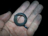
With me struggling to get the hub motor apart and back together again multiple times I had made the already damaged dry oil seal on the hub much worse. It had got to the point that the rubber oil seal was no longer keeping the metal spring inside it captive and it had been pulled out (by the magnets?) along the shaft towards the stator. The axle had been rubbing on this and it was the coiled metal spring that I was hearing scraping.
20190308_212341 (Medium).jpg
I ordered a brand new seal from eBay, packed it with lithium grease and fitted it and there was no more scraping sound. Took the ebike to work today and it ran sweet as anything. Many thank for all your help @amberwolf I really appreciate it :)
 
Back
Top