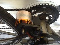
Looks pretty stealth to me. The controller sticks out a bit, but the hub hides nicely behind the cluster and disc.
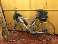
The battery bag is a bit in your face, but you were running the same bag for the friction drive set-up too.
Considering I only had 3 x 5S 5000mah packs in there, the aerowedge could have been used no problems. Just that I was carrying a charger and extra tools just in case. Certainly the aerowedge will look much better in relation to a stealth appearance.
1) How close were the riding/throttle styles? Did you use the hub at all from a standstill?
Most take offs were with a little assistance from the hub motor, a definite advantage for the hub but with a consumption cost of cause
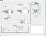
2) 15S @ 40Amps or 2000+watts for the hub. What was the friction drive restricted to? I find with higher power setups, I tend to us the assist more for acceleration, than maintaining speed which kills efficiency.
Friction drive was limited to 800W. I was very careful in the test to use only light throttle. I doubt I went over 800W during the ride. Because I had an adjustable throttle on my friction drive, I was using the friction drive to maintain speed also. I used the same riding style with the hub.
[3) What are the no load speeds of both setups?
I haven't checked this but I think the hub would win here.
4) How long does the wheel take to spin down from full no load, to rest when the wheel is in the air on both? It is a good sign that it feels free rolling on the road.
Spin down is very impressive. Like a normal bike freewheel.
5) Is the 4kg weight gain including battery, or not? Bit unfair if it includes battery as the wh's may not be the same.
I was carrying a similar amount of battery for both. The friction drive setup I was using on this bike was about a 1kg. The hub is 4.5kg and the controller is about 800G
Anyway you look at it the efficiency stats for the bike in either guise are pretty darn good. Well done on a beautiful build.
Thanks Adrian. I agree, the stats are great for both setups. To be fair, I think it is difficult not use the Hub more when riding even if you are trying not too. The power is seamless and as you pointed out, the drive is used off the mark.
I am surprised how close they actually are. After seeing SamTexas super economy figures, I was expecting kind of the same but it certainly wasn't the case for my setup. It could be argued that because mine is a high powered setup (couldn't help myself), this is causing the higher consumption. However, I was really careful to use very light throttle movements plus High Volt setups have a slight efficiency advantage also.
Need to mention the power available in this setup. I was shocked and super impressed. Being use to a 9kW Bomber everything else feels a little tame. This geared motor at over 2000 Watts feels more like 4000W and pops up the front wheel off the mark without a problem. Might need to hold a set of planet gears in stock just in case
")