izeman said:
teklektik said:
What is the source of this wiring diagram?
the source of the diagram? if i understand your question correctly: this is directly from justin's post.
Ha! You got me on that one - I hadn't realized at the time that the new V3 spec was already appearing in controllers and had sort of dismissed the wiring diagram in his post as a 'futures' item. Thanks for the heads-up!
izeman said:
teklektik said:
Are you attempting to add a CA connector to your controller which lacked it originally or to modify an existing V2 CA controller connector to be V3 compatible?
Apologies for some unfamiliarity with your controller connection labeling, but what is the relationship of SL1 to SP? Are these the same electrically? For a generic controller upgrade, the CA-DP(6) Throttle Out signal would go to SP (controller Throttle In).
lyen's controller has the CA connector installed. but i don't know if it's v2 or v3.
SP is fine for me. on the controller board there CA-DP(6) is connected to a diode, which itself is connected to SP. i desoldered pin6 and soldered it to SP directly. that made the ca thru throttle work. otherwise the wheel wouldn't turn.
Okay - good news that it's running. With the as-shipped diode hookup, it's V2-compatible, although if your board is actually constructed according to Justin's post, things should have worked using the SL1 connection. But - as long as SP is working out, the SL1 mystery can be solved another day...
izeman said:
the question remains if CA-DP(5) has to go to SA, or if it may stay connected to where it is - which is the pad where it should work with a v2.
It can stay where it is. Only the throttle connection differs between the V2 and V3 - all else is the same.
izeman said:
i read the whole setup guide and adjusted all min/max values, and it works really nice w/o any dead zones. to ask a precise question: what did you have to change to connect the v3 with connected throttle to a eb312?
thanks
")
Very glad to hear all is working well
.
Well, I have a bit of an unusual situation because of the dual motors, but the short answer is that I used the controller throttle connectors and no changes were necessary to the controllers themselves.
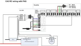
The longer story: I presently run two EB312s and originally ran a V2 with an older CA-SA external shunt and a wheel pickup - the CA controls/monitors both motors at once. I retrofit the bike with a V3 (with throttle support) but left the V2 shunt and wheel pickup in place. I run the CA Throttle Out through a couple of Schottky diodes (D4 and D5) and directly into the existing controller Throttle connectors as shown
here. Except for the diodes, this is exactly as Justin described in his post. All the other stuff in the referenced diagram other than the D4 and D5 diodes is for other functionality unrelated to making the basic throttle work with the V3 and two controllers. At the time of the V2 to V3 upgrade I was running Crystalyte controllers and subsequently switched to the EB312s as a
plug-in replacement - no wiring changes.