Cyclone 500W controller options

lanlijo

100 µW
Joined
Feb 27, 2012
Messages
7
Hey,

I'm a looongg time lurker, first time poster. In the past I've managed to get away with the search tool and lots of reading but I need to ask a question this time!

Background:
I have a XtraCycle Freeradical kit on my mountain bike to act as my cargo hauler here in Hobart. So we're talking hills and load. I live at 170m and use this bike to get eg 2x 25kg bags of chook food home from town (only 5km) or scoot out to Taroona (about 15km each way) with extra load.
After much deliberation I (now regrettably) bought a 2nd hand Elation v2. I wanted the triple freewheeling crankrings to allow for awesome torque with load on hills. The top speed was an added bonus but not the driving reason at all. I want a bike with extras, not an electric motorbike. The freewheel mechanism seems fine but the cranks are Terrible. I have twisted them both with nothing but the power of my legs on short steep inclines, which frankly indicates that they are just not built for actual bicycle use. I have never twisted any crank before no matter how cheap and nasty so that sets a new standard.
I have a new 24V 20Ah Ping battery which seems fine.
I am very happy with its pulling capacity and would actually be happy to have a bit less power (say 400W) if I got more range out of it between charges.
I can do basic electronic assembly but I don't really understand whats going on at a deeper level so need simple directions!


Current problem:
Anyway, last week I'm pretty sure I blew the controller board on the 500W headline. I was walking it uphill in the garden with 25kg extra load and under a small amount of power but in quite a high gear when the rear wheel got caught on a step and it just stopped (ie high load, low RPM) Nothing popped, fizzled, smoked or anything like that. The inline 30A fuse between the battery blew and on testing there are 0(zero) ohms across the main battery inputs to the motor/controller.
On opening it all up there is nothing on the controller nor throttle which looks remotely burnt charred or anything. The biggest chip on the controller has some difference in texture to its top but it doesn't look classically cooked and I think its just the way it comes from the factory.

I have read these:
http://endless-sphere.com/forums/viewtopic.php?f=2&t=22514
http://www.endless-sphere.com/forums/viewtopic.php?f=28&t=13423

plus quite a bit elsewhere.

I know the 500W kit is know for having issues like this and honestly, I should have just bought a 650W new from cyclone from the get go...

I emailed paco from cyclone as I thought that he might sell me an internal hall sensor PCB and a 650W controller but he says that the 500W is not upgradeable. That not what this forum led me to believe. I've asked him again in a different way now...

so:
1. can someone actually give more detailed explanations of how to hack my burnt controller board into a hall sensor PCB s othat I can use an external controller.
2. what controller would you actually recommend - 24V, 400-600W please. I dont want to have to fart around with my battery as well on top of all this.
I'd be happy with the Headline option (650W I believe) but have looked at Lyen and kelly but don't know if they will actually work in the way I am after... I'm not after more power like one of the posters above, I just want reliable electronics and low-medium speed torque.


thanks heaps!

lanlijo
 
There was a kiwi guy who did it IIRC.

If there is zero ohms between the battery leads you just cooked some FET's, rip out the garbage and put something decent in. There are pleanty of good low voltage FET's out there that can handle a LOT more current than whats in there. Test between the drain and source and you will probably find some that are dead. They only use six fets IIRC, with very little in the way of capacitance, no wonder they die.

I replaced the FETS in mine with IRF1405's 55V 169A(!!) 5.3mOhm - cheap (I bought them for $2.20 each in qty 1) Very Good.

You can mess with the shunts in these for higher power, but the combined heat dissipation of the motor and FET's is a bad combination.
 
heathyoung said:
There was a kiwi guy who did it IIRC.
I'm that kiwi :lol:, just replied to a PM from Lance with some notes on converting to an external controller.

Lance, if you think its just the FETS and you are happy with the internal controller then might bet best to try a new set before going all butcher like I did but on the other hand an external controller gives you more options and the heat is away from the motor. I no longer worry about water near the motor either.
Doesn't look as tidy with an external controller though although the little 6 fet ecrazyman is nice and compact and is all that is needed as an external controller for moderate power. Its throttle response is a bit rough at the low end on 57V though, not that you are looking for high voltage operation. There is a 24V version of the same controller available (looks identical).

My internal controller was really sick. I reverse polaritied it :oops: so I decided it was not worth fixing and the external conversion was the easy option... alright I had other motives like speed although I haven't needed to even swap from the stock FETs in the 48V 350W ecrazyman yet although I do have another one built up with 4110s for when I get time to try more volts. *glances over at a nice stack of new LIPO* being monitored for self discharge for a month.
 
what is the best mosfet to replace the standard mosfets in the 500w cyclone ?

is this the best ?

IRF1405's 55V 169A(!!) 5.3mOhm - cheap (I bought them for $2.20 each in qty 1) Very Good.


is it better then 4110 ?

Is their anything better?
 
The 4110s are fine if you can get them cheap - I couldn't at the time.
 
Well,

I should have checked this thread again sooner. Since I'd had no replies earlier I'd given up and tracked down ricky_nz who was very helpful and gave me the confidance to have a crack at hacking up my board...

I was just about to start ripping stuff out of the controller board since I have ordered a 6 FET LYEN mini monster controller along with a direct plug in cycle analyst... I looked at all sorts of controller options and went with this one based primarily on reports of good customer service, and secondarily that his baord will do 24V 500W whereas lots of thers need 36V+ for that much power. I'm not that fussed about customisation I'll get but maybe one day I will.

I guess I possibly could have saved myself $200 there which is a shame, but since I've spent it now I figure that I should make use of the better controller and just hack up the one I have. Otherwise I'm just spending even more money (albeit $10-15) and left with an unused external controller and DPCA...

I intend to take lots of photos to help anyone else who does this, and am just about to start de-soldering. If anyone actually can directly identify for me in advance which Hall sensor goes with which coil that would be great!

cheers

lanlijo
 
Ok,

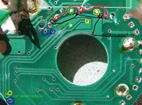
so, annoyingly, I even found 6 FETs sitting in a drawer which probably would have been fine - 60V and 52A which is plenty for my setup. But I've got the LYEN and CA coming, so the board got stripped down:

View attachment 1

I also removed the two biggest chips from the other side, just cut all the legs with small side cutters and pulled them out, very easy.

At this point, I was able to easily see the common power and ground traces going to each of the halls, and then shortly afterwards realised that the sensor legs also went through a 'dummy' 0 ohm resistor to a nearby pin out which then led along a trace to an even better located pinout near the exit point of the board! Yay!

IMG_1121b.JPG

the halls now draw just under 10mA under 5V which ricky_nz tells me means they are effectively isolated. This is in parallel, so I assume they are all working properly?

I didnt have to cut any traces at all, just had to remove parts which was really pretty easy. I could have actually just done it all with my little sidecutters.

I've had a good look at both sides of the board and can't see any definite connections between the sensors and the phase wires (they all go via the big chip of course...) but I'm just going to assume for my first test that they are lined up in the same order, because that just seems to make sense...

I haven't soldered anyhting back on yet becuase... see the next post...

cheers

lanlijo
 
So,
I haven't soldered anything back on yet, because I have questions about my wire gauge:

1. The hall sensors use almost no power, right? Can I safely use wire pulled out of a network cable or 2-pair phone line? It lookes about the same as the wire from the cyclone throttle (yes I know thats not the hall wires though..) and its the only stuff I have which is in lots of nice identifiable colours...
If not, could I use thicker wire for the power + & - , but still use the network wires for the actual sensors?

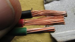
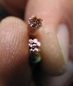
2. Do i need to use identical wire for each of the motor phase wires? I have a nice red and black wire from the original setup, but now need a third one. If necessary, I can cut the red in half and mark it clearly, but I also have some 240V australian mains power earth wire whcih is a convenient green colour. BUT its a little bit thinner, and has FAR fewer strands than the other stuff. My intuition tells me this is a bad idea as one pole might get slightly more or less power, causing some kind of badness, but I just dont know...

You can see the difference:

cheers

lanlijo
 

Attachments

  • IMG_1125.JPG
    IMG_1125.JPG
    78.1 KB · Views: 1,170
  • IMG_1129.JPG
    IMG_1129.JPG
    40.7 KB · Views: 4,856
oops, forgot to say I also uploaded more/ full resolution pics to here:

http://minus.com/m500WHeadline

I tried to link to them inline but it just put in 'Image" so I uploaded directly..

cheers

lanlijo
 
lanlijo said:
1. The hall sensors use almost no power, right? Can I safely use wire pulled out of a network cable or 2-pair phone line? It lookes about the same as the wire from the cyclone throttle (yes I know thats not the hall wires though..) and its the only stuff I have which is in lots of nice identifiable colours...
If not, could I use thicker wire for the power + & - , but still use the network wires for the actual sensors?
Yep the hall sensors only draw about 10mA so any wire that is physically capable of handling any vibration is usable. Smaller wire might make connecting it to the board easy. ripped up network cable should be fine. I have used network cable for halls before.
The multi stranded network cable is better than single strand as its more resistant to breaking when flexed.
lanlijo said:
2. Do i need to use identical wire for each of the motor phase wires? I have a nice red and black wire from the original setup, but now need a third one. If necessary, I can cut the red in half and mark it clearly, but I also have some 240V australian mains power earth wire which is a convenient green colour. BUT its a little bit thinner, and has FAR fewer strands than the other stuff. My intuition tells me this is a bad idea as one pole might get slightly more or less power, causing some kind of badness, but I just dont know...
The number of strands doesn't matter, its the total area of copper.
For the short distance a small difference in wire thickness shouldn't cause any major problems. Might mean one phase sees a few millivolts less but the motor won't notice it.
You could run two runs of the mains earth cable in parallel to get more copper if you want..
The wire in the photo is probably ok though. Just make sure it doesn't get warm enough to soften the insulation under load.

Just a warning when you get to the sorting out the hall sensor wiring go easy on the throttle when testing the motor unloaded. preferably use a current limited power supply rather than batteries if available.
if you just give it full throttle on the wrong hall sensor combination you might cook your new controller. I did my tests with the gearbox removed as that adds additional load.
 
Hi mate,

wished I checked the board earlier,

I am in West Moonah!!

anyway feel free to PM me if you have any questions on the cyclone, I am just building a 1200W 48v DH bike for my electrician, he could build a board from scratch but is not too mechanically minded!!

I am interested in the lyen controller as he was thinking of upgrading to a kelly or lyen as well!!

is the mini controller sensorless?
 
so...

its taken me a while to get back to thie post, what with life etc getting in the way it took a while to finish it off and test ride it enough to be confidant that its all good, but yes, I can definitely confirm that I have actually quite easily converted the 500W headline/cyclone/elation motor into an external controller model.

The Lyen is working absolutely fine, gets a little warm, but then again its crammed into a fairly small space with only average ventilation (I want it rain proofed ultimately.)
I guess its working a bit better than the cyclone one, it seems to work even when not at full throttle but really its very hard to be objective about this...

The cycle analyst has me pulling about 650W up hill with light pedalling. I would have actually been very happy with less than this to get better range, but to be fair, most of my trips are shorter anyway so its all good. Takeaway Thai dinner on sunday night used about 5Ah from my house in south hobart to sandy bay and back. Thats about 7km round trip with an elevation gain of 200m on the way home. Pedalling, but really just to keep warm as I was totally shagged from actually mountain biking that morning :)
I had similar wattages with an extra 50kg of chook food on board last week but don't know about how much juice I pulled out. Obviously it was much slower that time though!

regarding the actual work I had to do;

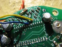
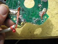
these are my hall sensor wires going to pinouts which are located near the original big chip which is obviously no longer there:

IMG_1148.JPG


and this is the other side, with them soldered in place, as well as the halls +5v. I just used two wires in parallel because, well, they were there in the cable I used! I ended up going to the tipshop and got a nice old pc cable of some sort for the hall sensor, similar thickness to network cable but better protected and with a more appropriate colour choice...

IMG_1151.JPG

and this is the horrible mess which nonetheless gave me a successful bench test:


In the end, I think I swapped the hall sensors around somewhere in the soldering process, so the phase/hall colours are actually out of match in a way, but it really didn't matter. I spent so long reading about phase/hall combinations but it was just soooooo easy. I powered up first time, eased on the throttle and it went jgjgjgjgjgjgjger, which was clearly wrong, switched two sensors at which point it went <silent>, switched another two, at which point it went zzzzzzsssssseeeeee beautifully. All in all I probably spent 2 hours reading and getting my head around it, and 45 seconds actually just switching wires.... (but with an understanding of why!)

I stuck a couple of other images, plus a couple of bench test videos here:

http://minus.com/m500WHeadline/


Now, my next plan is to complete my weatherproofing of the controller box, and then to make some protective battery containers and do a wee bit of cable lengthening so I can have one in each pannier. This is my cargo bike, so they will be bent from more tipshop sheet metal as I want to be able to confidantly stuff all sorts of stuff into the pannier and strap it down hard without worrying about piercing the Pings with an errant piece of metal one day... All this, unfortunately will have to wait until june as I am about to head off overseas, but I'll stick some more photos up when its all done, just for completeness.

cheers

lanlijo
 
damonjackson_spl said:
Hi mate,

wished I checked the board earlier,

I am in West Moonah!!

anyway feel free to PM me if you have any questions on the cyclone, I am just building a 1200W 48v DH bike for my electrician, he could build a board from scratch but is not too mechanically minded!!

I am interested in the lyen controller as he was thinking of upgrading to a kelly or lyen as well!!

is the mini controller sensorless?

uh, Damon,

to make the world even smaller, yes, I know that you live in West Moonah... I have been to your house... I have seen your bike...

You are currently drafting the plans for our house and shed extension in south hobart...

Anyway, the mini controller isn't sensorless, as you can see from my earlier post. I thought about going the sensorless intially but am glad I didn't as it was really easy and read of a few people not having any joy with the sensorless options (plus I don't really see how they will work with a non-direct-drive motor such as the cyclone.)

cheers

lanlijo
 
Hi lance,
lanlijo said:
so...

its taken me a while to get back to thie post, what with life etc getting in the way it took a while to finish it off and test ride it enough to be confidant that its all good, but yes, I can definitely confirm that I have actually quite easily converted the 500W headline/cyclone/elation motor into an external controller model.

The Lyen is working absolutely fine, gets a little warm, but then again its crammed into a fairly small space with only average ventilation (I want it rain proofed ultimately.)
I guess its working a bit better than the cyclone one, it seems to work even when not at full throttle but really its very hard to be objective about this...
Great to read you got it working :D.
Good photos and reference for others compared to the poor photos I had of my conversion.
Unfortunately I took me a while to read your success post. I've had too many other things going on over the last couple of months and hadn't really been near the sphere.

Ricky
 
it will be greentime controller 48v 45amps, huatong 48v 2000watts,,for cyclone. tested result good
 
Back
Top