Damaged A123 Battery Cans

markz

100 TW
Joined
Jan 9, 2014
Messages
12,179
Location
Canada and the USA
Heres my last 10 cans, I'm hoping from the ones you see below that I can use atleast 4, but I doubt it.

Should I keep them, use them in a pinch or as spares. Should I throw them away. What should I do with them?

For some of them, there is mild indentation on the side of the can, but some have the corner burred or dented.
My thought is the one I labelled as the worst, the damage is on the pos (+) side, the can itself is pos (+), but the chemicals inside act differently when theres damage like this right?
Also, the actual ring is not damaged at all except for 2nd most damaged one. When I say ring, when I have the can under magnify glass, there are smooth sides for the can, it then goes into a ring that I am thinking is like a cap (this is looking at it from the sideview), then theres a cover and for the pos (+) side another smaller cover as you can see. So maybe 3 I can use. The last 2 as shown below, and a choice of the last 3.

Your thoughts please.
 
How about you test them ?

IR, capacity, voltage/charge retention, temperature under load, etc etc ?
Compare to similar " good" cells of the same stock.

Just tried it, blew my 500mA fuse in my DMM. Couldnt read anything, since I began having troubles reading amperes a week ago.

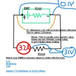
What I did was read 3.2Vcan(open), 1ohm coil nickel strip, should have read ~3A. Thats to get Internal Resistance.
Good thing is I just bought a laser temp probe a few days ago so I can measure temp when I replace the fuses.

How do I go about voltage/charge retention? Charge them up, and let them sit for a week. Or do I give it a load?
 
I think the holes ripped in the ends of the cans from spot welds ripped off are probably more of a problem than the dents, but I could be wrong, as I don't remmeber the thread that was discussed in before and don't have a handy link.
 
Well those bumps or ridges are from detabbing, I will Dremel down flush. I didnt think this would be an issue. But I will do a search of it myself amberwolf, thanks for mentioning it. The green insulation tube wrap as seen on my first post, I cut off to view damage.

View attachment 3

I have a pic of the original pack I bought used from a ES user from the For Sale Used section. These are bus batteries, you can see how much space is between the batteries. I overpaid for these batteries.

View attachment 2
View attachment 1
 
markz said:
Well those bumps or ridges are from detabbing, I will Dremel down flush. I didnt think this would be an issue.
At least some of them look like actual holes ripped in the can, especially clear (to me) in this image:
https://endless-sphere.com/forums/download/file.php?id=184950&mode=view
but in your latest image with many cans visible in the assembled pack, I see several with "bumps" around the former weld site that also look ripped out.

You might want to do some really close examination of them with some type of high magnification.


If the can is opened thru any of those sites, it's not sealed anymore, and moisture/etc can get in (and already has), and electrolyte might get out (might not have yet, probably depends on charge/discharge conditions and temperature).


It's been discussed in other threads about recycled cell packs over the years:

To prevent that kind of damage, cutting thru the tabs rather than removing them would be your safest bet.

This also gives you the option of soldering the pack together if all else fails, if you leave enough tab hanging off the top of each cell, like if you cut exactly at the point between cells, because you can use a clip of some type to heatsink the cell itself so it never sees the heat from the soldering.

Next best would be grinding very carefully thru the tab at just the weld points, using a fixture and jig that prevents the grinder from going any further than the thickness of the tab so it cannot touch the cell itself.
 
Great point, yeah I will definately try to get a better view of the damage from detabbing.

Thanks again.

I do understand what you are saying now, its odd that they put a smaller glued on flat piece to the + side of the can.
But that hole, is just that a hole on the glued on flat piece. Thats why about 3 of them ripped off, 2 of them I posted a pic above (4th picture above).
 
Yeah sorry, I do the same thing, I do too much editing. :lol:

This also gives you the option of soldering the pack together if all else fails, if you leave enough tab hanging off the top of each cell, like if you cut exactly at the point between cells, because you can use a clip of some type to heatsink the cell itself so it never sees the heat from the soldering.

Next best would be grinding very carefully thru the tab at just the weld points, using a fixture and jig that prevents the grinder from going any further than the thickness of the tab so it cannot touch the cell itself.

The thought did cross my mind when pondering how to take the original pack apart. Leaving the metal tab on to solder, it was a fleeting thought at the time (I realize now, I would have been way better off leaving the tabs and soldering wire to them). I was trying to think of ways to break it up in chunks and leave it original but for what I wanted the voltage requirement didnt line up to my wanted needs at the time. Plus the space between the cans is huge. I did not take a picture but you can see it with some of the cans removed and metal/insulation hanging. A good 1/4" to 1/2" between the cans if not more. I am pretty certain these cells/cans were used pretty heavily for that amount of cooling. I have not done capacity tests yet, but my assumption is from the 2.2 or 2.3Ah from original, I am hoping they are 75% to 80%.

Anyway here is the 3rd can of the 3 total with there glued on metal thats been ripped off from the (+) side, I think they place it there for a reason, maybe if they did tab weld it straight to can on pos+ side there might have been an issue. Left side has it removed, right side is still intact with the "hole" clearly visible, that does not go through entirely. I see no damage at all from removing glued of sheet (I need to give it a name, maybe the "mat") on the 3. The tab welds doesnt penetrate the actual can, just the mat, so its some sort of glue, or perhaps a light tinning. Im not sure.

 
So tell me, is 31.25 milli-ohms of interneal resistance good, average or bad for batteries that I bought used.

Here is my calculations using a Digital Multi-meter.
The internal resistance of my a123 LiFePO4 a123 26650-M1B.jpg

10mOhms stated here
If I have calculated correctly, your setup using two 45 Ah 12 volt batteries in parallel has 720 cold cranking amps. This implies an internal resistance of 16.7 milli ohms.

I think your calculation is a bit of, I get around 6.5 mohm. ( Ri=Udrop/I, R=(12-7)/(380*2)= 6.578 mohm )

Each A123 M1 cell is rated at 10 milli Ohm internal resistance according to the data sheet. So, three in series should be 30 milli ohms, then paralleling two sets of three in series should result in 15 milli ohms of internal resistance for the 3S2P pack.

So mine are 3x the IR as from factory. I wonder how much capacity I have lost, thats my next involved step.

Uh Oh - This guy chucks lipo's at 20mOhms

I really really really really hpope my undamaged cans are not this high in IR., but I got me a feeling they are all the same.
I think I got ripped off of my purchase, I really do now. Before I had fleeting thought. Damn for the money I spent of these, I could have gotten a super sweet deal from Tumich on cells. I really have to watch out on my impulse buys.
 
Hi all.

The pack these come from is air-cooled and does see very high C-rates at times, in both directions. It is possible to keep the weld straps and cut the whole into patterns that will work for you. This wouldn't work for the style holder you are going to, but you can often use heatshrink to make RC-style packs this way. You can put folds into the weld strap between the cells to get them closer together.

The extra disc on the + side of the can is, I believe, added for weldability to the nickel weld straps. The weld nuggets left behind are not a problem per se, unless they get in the way of you attaching to the cans. You really should not have removed the tabs at all. You can solder to those very easily and safely, which is definitely not the case with the raw cells. So you've made these cells very difficult to work with at this point unless you have a tab welder. Further, you seem to have done significant damage to the cans during removal from the module. This may or may not be a problem. This CAN cause an internal short, but you would know about that by now. If you're holding voltage OK, do an HSD (high self-discharge) test on the cells. I have described that test on here a few times before. A capacity test would also be good--be sure to charge fully (3.60 Volts per cell, charge current fallen to near zero). Discharge at 1C until loaded voltage falls to 2.0 Volts. If they test OK, I would use them, but make sure they don't see any more damage. Don't leave the cans exposed, try not to cut that insulating sleeve if possible.

As far as your impedance test, I would want to see your rig before putting any faith at all in the numbers you're getting. How are you attaching to the cell while insuring you aren't adding 20 mOhms or more of impedance at the connection points? Clip leads don't cut it for that test--you need HARD, SOLID connections at every point in the circuit and all conductors have to be capable of carrying the rated current without meaningful voltage drop across them. It is VERY easy to "see" impedance that isn't really there if you don't adhere to these guidelines absolutely. I've seen thousands of these modules and the rise you report here seems very excessive--especially if none of the 96 cells in that module were toast when you got it. (I would hope you paid based on the number of cells, not the amount of "air" between them.)

The little circle in the center of the negative terminal is not the vent. There is a stainless steel pin in the center of the jelly roll in the cell, this is one end of it. The ends of the can are welded on (also not the vent location). The vent is that trough around the circumference of the positive end of the can. It is a "thin spot" etched into the end. I have never seen a cap weld break or leak except with severe impact. The plastic insulator around the negative terminal prevents the negative weld strap tabs from touching the can, which would create a dead short across the cell. Do not remove it, it's critical to safety.

Hope that helps.
 
Wow! Thanks very much wb9k, that does indeed clear lots of things up for me.

My I.R. connections were not all that great. I will do it again with more solid connections.

Out of 92 cans, only 5 have physical damage (The ones I posted) due to detabbing, and I did have one can go bad. I damaged it so bad, accidentally of course, that it just heated and heated and heated, Thermal Runaway I think is what its called. I could see shortening lighting strike, heck I could have been looking straight into the can. I should have left the tabs on, but I dont mind retabbing them. Just means I learn more. It was an involved process for detabing, and I was trying my utmost to be careful.

Here is an interesting thing on three of my other cans. These were apart of the ones I put aside for further inspection.
View attachment 2
View attachment 1
 
Ugh...salty corrosion. You'll want to clean that off as best you can. I would treat these cells (as well as your other dinged up ones) as spares if you can. Any cans that have corrosion that extends into the trough of the safety vent should be discarded. If there's no corrosion in that trough (and yes, you'll have to cut away a bit of the plastic sleeve to inspect the safety vent feature as well as get off any corrosion that's under the plastic), then the cell can be cleaned up and safely used. Light scrubbing with a soft bristle brush followed by compressed air followed by freeze spray (just a few direct hits, each from a different angle) will get the cell surface nice and clean again. Try to keep the cells really clean and dry at all times to prevent future degradation. And of course, keep your nice shiny cells clean and dry so they don't look like these three in a few years. Dirty water that can collect and sit for long periods of time on the can is your enemy!

How hot did the cell that you shorted out get? Too hot to hold? We had a 32113 fail like that with just a tiny puncture in the surface in the lab once. It got obviously warm, but you could handle it through the entire event. A tiny amount of electrolyte gurgled through the hole. After a few minutes, it was over, no big deal at all. That is NOT thermal runaway, which ends in an uncontrollable fire. This is an important distinction, and A123 cells do not thermally run away in cases of even severe short circuits. Worst case is generally that electrolyte will spray from the cell AND there's an ignition source handy. The electrolyte mist is flammable and will create a short-lived "Roman candle" effect if ignited while actively venting from a cell--and that fire will be hot, though much cooler than other Li ion chemistries. Ignition is rare, but can definitely occur. A little bit of dribble is nothing to panic about, but keep it off your skin and out of your eyes.

Unless a few cells were already missing, there should be 96 cells there total (12 series elements of 8 cells each). Sounds like most of them are still in good shape, so that's good. How many were you planning to use for your project?
 
How hot did the cell that you shorted out get? Too hot to hold?

How many were you planning to use for your project?

Yes it was too hot to hold, what had happened was I punctured it in some way I believe it was at one of the corners, most likely the neg (-) side.

I have not really decided yet on what I want this high discharge pack to be yet. I have reconfigured it into 2 different sizes now. The latest, is two packs of 4P8S, with 14 extra good batteries, and 5 damaged. I am still waiting on my Tab Welder Timer package, regular post from UK. I am in no rush as theres snow on the ground here. I am building a Transformer Tab Welder. I have to look at whats available for chargers. From EM3EV there are 12S, 16S, 20S, and 24S so it seems they come in multiples of 4S. I more then likely will buy a Mean Well PSU. NES model, in the 10A range.


I count 91 cans on hand, add in the extra one, is 92. I wonder where my other 4 are. Hmmmmm interesting.
Original pack was 16ah 40v with BMS.
 
Should I build the pack to 16S or 14S, minor difference in speed, big difference in distance (Ah).
I see EM3EV has LiFePO4 chargers available in 12S, 16S, 20S and 24S.

5P16S - 58.4V - 10Ah - 51kph - 22km @ 100% throttle or 38km at 60% throttle.
*******Notice how there is not much difference at all between the one above and below at 100% or 60% throttle.
5P14S - 51.2V - 10Ah - 45.8kph - 20km @ 100% throttle or 39km at 60% throttle.

6P14S - 51.2V - 12Ah - 45.8kph - 24km @ 100% throttle or 47km at 60% throttle.
This gets me more cans to put in parallel to get an extra P in the configuration. This is what I am tempted to config the pack too.
I'm hesitant because its 14S I dont see any chargers in the config for lifepo4.
 
Back
Top