Destroyed my CA3?

Warekiwi said:
I tried your suggestion today- used the LED+ together with a common ground (not LED- this time) The screen lights up with the message "SLOW PMR UP" I assume this means that the MCU is OK?
Most likely the CA is intact except for it's battery-voltage-power-supply.

You can do what it says at that linked post to run it that way or fix it, or contact Grin to send it to them and they'll fix it.

After I damaged the battery-voltage supply when I first got it, I ran mine for quite a while on just that method (since I already had a 12v lighting supply battery on the bike), until I fried the actual MCU with the hall wire thing.

Now I guess I need to try with everything plugged back in and see what happens--
Before you do that, double and triple check all the wiring for shorts, broken insulation, etc, and open the controller to make sure no wires are pulled loose inside, or ends might be floating around waiting to short to something random.


just hope that the Hall sensors in the motor haven't fried?
If the wiring all checks out, and the system doesnt' run right but does run (offground at least), then you can test the halls via the steps at Grin's Learn-troubleshooting page.
 
Thanks again- I've emailed info@ebikes.ca to ask about the possible repair of the CA3 and given them the link to our chat here. In addition I've read their excellent troubleshooting guides regarding the testing and repair of the hall sensors. looks like I have some work ahead of me! I do have a 12V circuit for lighting etc. on the Quattrovelo (separate battery or converter from the 48V battery) so that option is available as well!
 
Further to my previous- I'm weighing up just buying another CA3 against either sending the dead one to Canada for repairs or using your idea of a separate 12V supply . I've removed most of the setup and wiring from the Quattrovelo and also tested the hall sensors in the Smart Pie motor. So far it seems that one of the hall sensors may have died but I'll dismantle the motor and look more closely. Two questions arise-
1. Looking at Hall sensors from various sources online there seem to be two major types- "latching" amd "non-latching"-- can you (or anybody) suggest a particular type or spec? From what I read it is recommended to replace all three at the same time? (It's a big job on the QV to remove and dismantle the motor so not something I want to again very soon!) I have read the excellent instruction on the GRIN website.
2. As "most" of the system is now sitting on my bench and thus easier to inspect and test. Is the throttle necessary to boot-up the CA3? (Removing it from the QV is a big job as the cable winds through the structure to the "tiller") -I thought that after checking all the removed system (motor, Controller, and CA3) I would have one last go at testing before I embark on fixing or replacing the CA3 and/or Hall sensors. (I've tested the Controller MOSFETS which seem OK but CA3 remains dead when connected to Controller and Power )

Thanks for the help so far-- I'm learning fast!
 
Warekiwi said:
Further to my previous- I'm weighing up just buying another CA3 against either sending the dead one to Canada for repairs...
You don't have your location filled in your profile so no way to tell about geographic issues. Ignoring customs, shipping, and other transport problems, it's pretty clear that a new unit will solve the issue the fastest if you want to get on the road ASAP at the end of the Summer in the Northern hemisphere. Otherwise, repair is the best option since it's guaranteed and low-effort at your end. Further hacking with external supplies is silly - you end up with a compromised unit and other DIY dongles - this is a solution to pursue only if actually getting the unit to and from Grin is a major problem. A third option here is to buy the new one, send the old one back for repair then sell it here on ES and take a 30% hit on price. It will sell fast and you won't be out the full cost of the replacement.


Warekiwi said:
Is the throttle necessary to boot-up the CA3?
No. The CA boots without any knowledge of the attached accessories and operating with no throttle is supported as a standard mode.


Warekiwi said:
Removing it from the QV is a big job as the cable winds through the structure to the "tiller"

I might recommend installing a pair of matching 6pin JSTs shortly after the CA so you can remove it from the Velo and leave the frame harness in situ. This will have negligible effect on operation and the added serviceability is well worth the effort - as is the case now for example... (I have this on my cargo bike with custom thru-frame wiring). Keep the relative connector sex the same (male on the CA) so there will be little chance of shorts with the CA removed (you can just plug a throttle jumper to the controller and run with the CA unplugged if you wish).

  • FWIW - Be advised that Justin has been away on Sun Tour for many weeks and is doing the marriage/honeymoon thing this month. That coupled with summer vacations for everybody else makes emailing and resolving technical problems very much slower this summer. This is a very unusual situation for Grin which is usually terrifically responsive. That said, simple stuff like sales should not feel the effects so much (if at all). Just something to consider when selecting options...
 
Thanks again Tek!
I've taken your advice and ordered a new CA3 from the UK sellers Jozztek (not far from Ware "where" I live 30km north of London) and will then do as you suggest and send the dead one to Canada for possible repair.
Re the suggested extra cable plugs- actually because of the lengths involved there is already a plugged in extension to the main CA3 plug making it fairly easy to remove- the tricky bit is from the GRIN controller to the Smart Pie motor where it is threaded behind some carbon "double walls" (I may have to see if I can splice in an extension there to improve the motor/hall connector access) . The thumb throttle, e-brake (used as shutoff only) and analogue pot cables run down the tiller shaft via a circuitous route to the CA3 plugs and are the most difficult to fully remove. Having said that- the system worked extremely well for around 2000km of extremely variable road conditions in the UK and France and problems only started when the Grinfineon controller came off its mountings on a bumpy/fast decent and temporarily hung on its cables breaking one or more connections.

Any suggestions on my other query about Hall Sensor types and the necessity of changing all 3 instead of the known faulty one??
 
Honeywell SS411A is a common motor choice - bipolar and good to 150degC. You can get them from eBay, etc but genuine parts can be had from parts supply houses - although these places can be costly because of shipping and (sometimes) minimum quantities. SS41 is similar and also works fine.

As for swapping one or many - flip a coin. I'm a firm believer in "If it ain't broke, don't fix it" but some may argue that a heat-induced hall failure has compromised the siblings and their little clocks are ticking. See how the job goes for the faulty one, then you can evaluate the effort/difficulty for your particular skill set before attacking the other two.
 
Warekiwi said:
I've also tried powering the Grinfineon without the CA3 but with the throttle and HALL plug plugged directly directly into it. The LED on the controller flashes MOST of the time indicating sensorless operation and the motor runs-- randomly the LED goes steady indicating that it's in sensor mode- I guess this suggests either a Hall sensor's failed or an intermittent cable fault.
Further to my previous- (using the methods on the GRIN site) I carefully tested the Hall sensors in the Smart Pie and also the Mosfets in the Grinfineon 25A controller. It seems that one Hall sensor PLUS at least one Mosfet in the controller have failed.(the Mosfet tests are a bit inconclusive using my "auto-rangeing multi-meter)) I have bought a new CA3 but am reluctant to connect this after destroying the previous one. I've checked all the wiring and as far as I can see there was only ONE failure there (the wire from a Hall sensor to the Grinfineon) It seems weird that that caused the cascade of events effectively destroying a Hall sensor, a Mosfet AND the CA3!
Having carefully opened the controller I think replacing a Mosfet would be beyond my dexterity and eyesight! Suggestions welcome.
 
Warekiwi said:
I've checked all the wiring and as far as I can see there was only ONE failure there (the wire from a Hall sensor to the Grinfineon) It seems weird that that caused the cascade of events effectively destroying a Hall sensor, a Mosfet AND the CA3!

Based on my own experience, the only type of fault that would destroy the CA3 and the hall sensor and potentially a FET at the same time would be a direct short between the hall sensor wire that is used as the speed sensor for the CA3, and a high voltage source like a phase wire or a battery wire.

In my case it was the battery wire, at an external Grin shunt. In your case, it's much more likely to be in the motor-to-controller cable, almost always at the axle, typically just at the axle exit but could be anywhere from inside the motor to that point. Can also be anywhere along the cable. The problem could be intermittent or it could be continuous.

If you can't see a problem, it doesn't mean it isn't still there--a tiny break in hte insulation where wires press together is all it takes, and when you pull the wires apart from each other such breaks can "heal" enough to be invisible without sufficient magnification and light. :( (and a continuity test will not show a problem at that point either).

If the circuits inside the CA lasted long enough before failing, or failed in a permanent short to ground or battery positive, they could have blown the FETs on the phase that is connected to the phase wire. Or there could be more than just the one phase and hall wire that's shorted inside the cable.


You can prevent such a failure from being possible by using an external speed sensor on the wheel, disconnecting the CA3's wire that goes to the hall sensor and connecting it to the external sensor. Normally I'd recommend opening the CA3 and soldering in a sensor (either from an old bike computer, or from Grin), but it might be easier for you if you use the CA3-DPS version from Grin instead of just the CA3-DP, so it already has the work done for you.


Then the CA3 is not connected to the hall sensors at all, so no matter what happens between motor and controller, the CA3 is isolated from them completely. Even if the motor and controller catch fire :lol: then the CA3 is unaffected unless that end of the bike burns too. :p


Since your CA3 wasn't fried completley like mine was, then your failure may not have been the same cause, but if you wish to ensure it can't happen in the future, the above would do that.

There are still other failures that can occur from wiring shorts, but direct high voltage into the CA3's speed sensor line isn't one of them at that point. ;)
 
Thanks Amberwolf- I've been away for a bit, so now I'm just getting back to trouble-shooting this problem. I'v got a new CA3 (updated to latest f/w) plus a replacement 25A Grinfineon controller. One of the motor halls has been replaced. Because of the "tricky" cable exit from the Smart Pie I've found it very difficult to thoroughly check the wiring from the inside of the Pie to the external connectors. (It looks OK where I can actually see it)

Note: My CA3(s) are the version pre-wired for external wheel sensor- disabled for the bench testing.

Current state of play-(all on bench as access is difficult when remounted)
1. With Halls and CA3 plugged into Grinfineon, Throttle connected to CA3 and wheel speed sensor disabled in CA3 setup.
- motor responds to throttle BUT only starts 90% of the time- if manually rotated will then start. (This would be impossible when remounted in velomobile as there are free-wheels in system to prevent drag from motor effecting unpowered pedaling and motor is virtually unreachable when refitted in nose of machine)

2.If Halls disconnected/unplugged then controller LED flashes (as expected) but motor will not start- it just vibrates(quite forcefully) and doesn't respond to any manual attempt to start .

Could this situation be an indication of a wiring fault from motor phases to external controller? I have another motor arriving soon to try out but would like to get the original motor working if possible.

All suggestions appreciated! (along with some method of checking phase wires externally using multimeter?)
 
Warekiwi said:
Current state of play-(all on bench as access is difficult when remounted)
1. With Halls and CA3 plugged into Grinfineon, Throttle connected to CA3 and wheel speed sensor disabled in CA3 setup.
- motor responds to throttle BUT only starts 90% of the time- if manually rotated will then start.

  1. It's not necessary to fiddle the CA config if the speed sensor is not working - the CA doesn't really need one to operate.
  2. If you have any doubts that the CA is interfering with operation, just configure the throttle to "Bypass" mode. This is a later feature that just routes the operator throttle to the controller without messing with it - must easier than the old "jumper the throttle around the CA" hardware strategy.
  3. 'Intermittent start' and 'starts when rotated by hand' are classic symptoms of a missing hall signal. The wheel stops on the dead hall and the controller becomes confused about the wheel position, but once moved by hand, runs on the remaining halls. As a first step, you should re-test the hall signals, probing the back of the controller side of the hall connector to verify that you are firing on all three cylinders up to that point.
  4. If the hall signals look good going into the controller then here's some instructions for checking the motor phases: Testing Controller and Motor with or without DMM. Frankly, this doesn't sound like a motor phase issue, but if answers aren't coming your way, a little less reasoning and a little more blind searching can be revealing... :D
 
Warekiwi said:
1. With Halls and CA3 plugged into Grinfineon, Throttle connected to CA3 and wheel speed sensor disabled in CA3 setup.
- motor responds to throttle BUT only starts 90% of the time- if manually rotated will then start.

That's probably a hall issue.

Could be:
--the replaced hall is installed upside down
--or defective
--or the wrong type
--or a hall signal wire is broken
--or still shorted to something, if you never found the original wiring failure and fixed it--if that's the case the new controller may also be damaged now too.
--or that during replacement another hall was damaged
--or wire broken from one to the rest of the system.

It could even be that the wires to the halls werent' secured well enough and they're being rubbed on the motor cover plate, and it's taken insulation off of them and shorting them to the cover. I had this happen on my leftside trike hubmotor a few days ago, and thankfully it didn't damage the controller, but it did break at least one hall. Controller is sensorless so doesn't matter for me, but yours would.

It's also possible it's the wrong hall/phase combination, but if the same combo worked before, it should also work now, assuming the new controller is wired the same way inside as the other was. Sometimes, even with an "identical" controller, the wires get soldered in a different order for halls or phases on the board inside. That means you either have to fix that to make them match the original controller, or you have to redetermine the phase/hall wiring. Or use the Learn function of the controller, if it has one.


Could this situation be an indication of a wiring fault from motor phases to external controller?
Unlikely, or it wouldn't keep spinning on just two phases, or would run REALLY rough if it did.


Untill the wiring inside the motor is checked by opening it up and closely examining it visually, which may require pulling the wires out of the axle exit to see the individual wires in the bundle, you won't know if there is a problem there or not. If there is one, then it could continue to damage anything that is connected to the motor, if a phase wire is shorting to a hall sensor signal even intermittently.
 
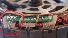
Thanks Amberwolf AND Teklektik for your ideas-- I'm sure that you are correct because I see that one of the Halls was replaced earlier (NOT by me!) and seems to be mounted slightly proud of the stator thus possibly rubbing on the rotor magnets. I also note that the leads from the replaced Hall have been routed OVER the little PCB and could be shorting intermittently. Having destroyed both a CA3 AND a Grinfineon I'm now reluctant to risk any more destruction so will wait until an engineer friend of mine (with better eyesight and dexterity!) visits and we can apply two minds and greater soldering skills to the problem.
I've bought some more Hall Sensors which brings up another question-- what is the convention regarding the three wires from a Hall detector (I assume that there is an earth, power and output??) See attached photo of the Smart Pie Hall setup.SmartPiHalls1.jpg
and here is the Hall pcb from above showing the possible cause of short circuit as leads are above the board NOT below as original-
(1) shows leads incorrectly positioned and (2) shows Hall sensor slightly "proud" of stator.


Once the Halls are sorted then we have the more difficult task of checking/repairing the exit wires from the motor through the axle. (Three phases and five Hall sensor and power wires)
Thanks again!
 
Finally- my friend visited and we rebuilt the motor and rewired all the leads that exit via the axle. Using one of those Chinese "test boxes" we tested the three motor phases and Hall sensor leads and all seemed OK. The motor seems to run OK "MOST" of the time BUT suffers from a new intermittent problem!

When starting from stopped (in a suitably low gear so as not to overload the motor) the motor is "jerky" (i.e. seems to pulse) Once speed builds up it seems to behave normally. I'm going to re-calibrate the throttle settings on the (new) CA3 today and see if that is the problem.The CA3 is using the latest firmware but is using the setup file copied from the earlier destroyed unit. I've tried "passthrough" and "current" setting for the throttle settings but the problem is unchanged. The controller ohms and calibration have been corrected for the new motor/controller installation. Any suggestions??
 
Finally answered my own questions and learnt a bit in the process! I spent some time following the throttle calibration procedure as detailed in the CA3 instructions- it seems that the parameters were significantly different now that the motor/Grinfineon/CA3 all changed. (Initially I just reloaded the config data from my previous setup using the PC connection) After a lot of "faffing about" I discovered that the throttle output from the CA3 was overloading the Grinfineon which was "tripping" Now the throttle input and outputs are correct the system runs extremely well AND very smoothly! I've also relocated the Grinfineon to a position where I can see the red LED- previously it was deep inside the machine so I hadn't noticed it occasionally flashing. Thanks Amberwolf AND Teklektik for your help and patience!
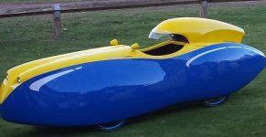
QV_small.jpg
 
Back
Top