Dewalt 36V (inside the charger)

Doctorbass

100 GW
Joined
Apr 8, 2007
Messages
7,499
Location
Quebec, Canada East
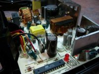
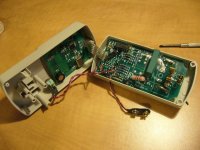
I just received my DC9000 charger today and i toke a coupple of pics inside:

note that all caps inside are rated 105 degree C... sounds good!

I will try to remove the board and keep it with the pack. I will only need to connect a 120V plug to my ebike...

Doc
 

Attachments

  • P1020115.jpg
    P1020115.jpg
    40.9 KB · Views: 8,721
  • P1020119.jpg
    P1020119.jpg
    48 KB · Views: 8,721
  • P1020117.jpg
    P1020117.jpg
    51.2 KB · Views: 8,725
  • P1020111.jpg
    P1020111.jpg
    32.4 KB · Views: 8,715
  • P1020113.jpg
    P1020113.jpg
    36.3 KB · Views: 8,720
  • P1020110.jpg
    P1020110.jpg
    43.4 KB · Views: 8,715
Humm.. that's a good question, BUT.. not without answer!.. I will unsolder it and see with electronic engineer at my work, i think they have an eeprom programmer :wink:

That would be good also to do the same with the internal BMS MCU IC of the battery!

From now, we have a part of the plan, an image of the board done with the "magic sauce" by removing the "epoxy" and an X-ray of the BMS..

Having the code would mean possibility to modify it to be charged differently than the dewalt charger and to set the min cut off voltage lower than around 30V and to fast charge those to 15min at 38V 10A..

I found that about the A123 charge/discharge recomendation:... quite more than on the A123 website!!!


http://www.first-products.de/specsenglisch.htm

Doc
 
Another details about the dewalt charger:

it take 80Wh from the 120V outlet to charge one battery pack from complete disharge (60Wh out from the pack) to complete total charge

Tat's a charge efficiency of 75% !!! i'm impressed!

I used one of my kill-a-watt power meter:

killawatt1.jpg


details at:
http://www.the-gadgeteer.com/review/kill_a_watt_electric_usage_monitor_review

Tat's a good gadget and very usefull... i compared it with my fluke and it is very accurate!!

I also took one and converted it to a DC power meter or audio power meter by supplying it with a external 9V battery. it work good too!.. the active or reactive power are metered!... it's usefull with ac load that the power factor is lower than 1.0 to see the real rms power and not simply V x A.. it take account of the unphase between current and voltage.

I got 10 for 290$ at ebay

Doc
 
Doctorbass said:
I used one of my kill-a-watt power meter:
I also took one and converted it to a DC power meter or audio power meter by supplying it with a external 9V battery. it work good too!.. the active or reactive power are metered!... it's usefull with ac load that the power factor is lower than 1.0 to see the real rms power and not simply V x A.. it take account of the unphase between current and voltage.

Hey Doc,

Could you show us how you modified the killawatt?

Also, can you diagram your measurement points: connect what-to-what? Motors/batteries/audio

Many thanks!
 
I only removed the internal 3W resistor that supply the board via the 120V using the high pass principle and a zenner diode and a 7805 voltage regulator.

Just connect the 9V to the input of the regulator and remove the resistor.

I will try to post a picture of that installation.

I also found how to calibrate it!

that's a combine of some botton you need top push in same time to enter the calibration mode. it is made to be calibrated using 100V and 10A source... (a 1000W 10 ohms non inductive resistor!)

but i tried to use only 10V and 1 A to get x100 factor reading to increase the resolution of the kWh reading from 10wh to 0.1wh.

It work well but i got a little offset i need to compensate.

tonight I will remove the Dewalt charger case and to only install the board on my ebike. i will only need to plug the bike on a outlet without removing my pack

Doc
 
Hey Doc,

you did not show us any pictures with the dewalt packs on your bike i would love to see the whole set up
 
Just thought I'd mention that isn't a pic, but an Atmel Atmega microcontroller. The program in the flash memory is read/written using a programmer via SPI sync serial (which is usually just another Atmega which goes from async rs-232 on your computer to the sync serial SPI.) But, I think they usually set the fuse bits in the microcontroller so you can't read it or modify/reprogram it.
 
TylerDurden, I have something for you:

Here are some pics of my first power meter:
using P4400 kill-a-watt.


ALSO!

Here is how to calibrate it (setup menu trick)

-----How to calibrate the Kill A Watt-----


Somehow set up a 110VAC 10.0A load. Probably best if it was resistive.

1. Push "Volt" and "Hz" at the same time to get "oPEn" on the display.

2. Push "Watt" until "C110" is displayed (C220 calibrates it for 220VAC).

3. Push "Hz". This is like an 'enter'. That should tell it you want to
calibrate for 110VAC

4. Push the "Watt" button until "SAVE" is displayed.

5. Push "Hz" to enter the calibration. The meter seems to think for two
seconds (probably doing the calibration) and then the voltage and current
will read true.


:wink:


Doc
 

Attachments

  • the switch placement.jpg
    the switch placement.jpg
    31.7 KB · Views: 8,421
  • Power meter using p4400 killawatt.jpg
    Power meter using p4400 killawatt.jpg
    35.8 KB · Views: 8,418
  • P1020381.JPG
    P1020381.JPG
    57.1 KB · Views: 8,874
  • here is the wiring.JPG
    here is the wiring.JPG
    74.7 KB · Views: 8,416
fechter said:
That does look like a good design.
I wonder what the code in the Atmel looks like?

0602 --> Second week Anno Domini 2006
 
Doctorbass said:
TylerDurden, I have something for you:

Here are some pics of my first power meter:
using P4400 kill-a-watt.


ALSO!

Here is how to calibrate it (setup menu trick)

-----How to calibrate the Kill A Watt-----


Somehow set up a 110VAC 10.0A load. Probably best if it was resistive.

1. Push "Volt" and "Hz" at the same time to get "oPEn" on the display.

2. Push "Watt" until "C110" is displayed (C220 calibrates it for 220VAC).

3. Push "Hz". This is like an 'enter'. That should tell it you want to
calibrate for 110VAC

4. Push the "Watt" button until "SAVE" is displayed.

5. Push "Hz" to enter the calibration. The meter seems to think for two
seconds (probably doing the calibration) and then the voltage and current
will read true.


:wink:


Doc

is it possible to set the kilawatt to 240v ac? i can't find anything like this in Australia!!!! :(
 
Yes it is possible. just follow the calibration setup instructions shown on that post (h 8:56)
 
Going back to original topic of DeWalt charger. Board is not potted like Milwakee charger which makes mods easier, but why would you try to modyfy.
Believe me, DeWalt made damn sure to choose optimal working on charging to mainain long battery life and deliever amps for jobs like cicular saw.
Doctorbas, I carry on my bike 2 charger boards stripped from box with slighly bent heatsinks to make them flat to fit into Pelican case whith all switches for battery configuration and power cord.
Baauty of this is that after reconfiguring batteries/separating/ I just plug the plug, turn rotary switch to position one I charge 2 packs at the time.
Before I was carrying charger in my backpack and had to constantly think:do I need it today?
I keep Pelican case fully opened during charging . I made some holes at the bottom of the case removing purge valve , because the box is not sealed any more, it is sealed where is important on the top and around sides. If there is some water pentration my boards at at the upper portion of the box as well as switches.
Anyway chargers like these are designed for harsh environment like constracion site where they got abused all the time.
It would be good to have fan blowing between sandwitch boards, but water proofness is a worry. Just whatever you decide to put chargers into - always enter wires from THE BOTTOM of the case - we cannot beat law of gravity.
Beauty of DeWalt or Milwakee or any other "ready" cordless adaptation is that you use system designed for longevity and abuse of batteries and massivly made, means low price.
MC
 
about the dewalt charger - does anyone have any suggestion on how to modify the board to make it work on 240V? (besides the external transformer..)
 
itron said:
about the dewalt charger - does anyone have any suggestion on how to modify the board to make it work on 240V? (besides the external transformer..)

hi Itron,
You can buy a 240v version of the charger buddy :) We sell one in australia for about $239 AUD. Check your local PREMIUM hardware store, you might be surprised (i was) - nb i was also shocked when i found out the local prices;)

edit: get someone over here to buy you and ship a 240v charger to you, is also an option.
 
Simply add a 3A diode in serie with one of the 240v wire. :wink:

It should be ok. that will cutt one of the 2 phases od the 240 and drop that to 120V. The cap inside will do the rest of the job by integrating all the dead time between missing phases.

These type of 'adapters' are next up in the price scale. They work by clipping out 1/2 of the AC wave form. So, instead of getting 240v full wave, you get 120v half wave. Some smarter ones work more along the ways that a light dimmer works (using a Triac), and will quickly turn on and off the power as it passes though to get close to 120v

Often, the board of the 120V charger is same then the 240V.. only a "jumper" or a different wiring of the transfo of the input make the diffenrece for each voltage value.

see exemple here (that will be the green wave you will get from starting with the red wave)

http://en.wikipedia.org/wiki/Image:Rectification.svg

You can also put a 120V MOV to avoid high voltage spike resulting from the phase cutting. (but this is not absolutly necessary)


To test it before, you can simply use a 120V 100W bulb and mesasure the
voltage across the post and if you get around 110-130V this is OK.

Doc


Doc
 
thanks for the great info. we are just getting settled in to our new home and i am just now getting back to work on my a123 setup.

most of the micros with eprom have a security fuse that prevents you from reading the code. i would be almost certain that will be what one finds when trying to dump the milwaukee code.
 
What are the charger's outputs? Just one positive and one ground wire? I'm hoping so because I'd like to replace the default charging mechanism with a simple plug-in connector. Otherwise I'd have to remove each battery from the pack to charge it.
 
the charger has connections to each cell through a pair of flat cable connectors on the cage that contains the cells. it is much more than a simple two wire system.

on the other hand, i have been playing with a pack i am willing to damage, and have deliberately overcharged and over-discharged cells with no problems so far. i have discharged to 2v per cell then hooked a 10 cell series pack to a cheapo 36v SLA charger that terminates at 41V. the pack charged up just fine with only a 10 degree F temp rise, and delivered the rated capacity when discharged at 15A.

of course this kind of abuse is bound to shorten the cycle life, but it does serve to help convince me that the data a123 provides is reliable.

just for kicks, i hooked up 4 series cells and used it to start my V8 truck. the cells provided over 100A without any complaints. these are the batteries we have been waiting for :)
 
bobmcree said:
just for kicks, i hooked up 4 series cells and used it to start my V8 truck. the cells provided over 100A without any complaints. these are the batteries we have been waiting for :)

That's very impressive -- would make a good TV advertisement.

LiFePO4 is still way too heavy to be the battery I'm waiting for. In the weight department, batteries (and other electrical energy storage mediums) still have a long way to go to out-compete fossil fuels. If this energy density chart is correct, gas beats the lightest rechargeable lithium batteries by a factor of about 50:
http://en.wikipedia.org/wiki/Energy_density
Though the electric motor's ~4X better efficiency cuts that advantage to a factor of 12 or so.
 
LiFePO4 is still way too heavy to be the battery I'm waiting for. In the weight department, batteries (and other electrical energy storage mediums) still have a long way to go to out-compete fossil fuels.

i do not expect to live long enough to see the medium you are waiting for. if the human race survives another 50 years i expect we will have fusion under control, and that is obviously the power source to use, since it has been powering the universe for awhile now. unfortunately, the fusion power sources do fail occasionally resulting in something just a bit worse than a lithium pack meltdown :)
 
bobmcree said:
just for kicks, i hooked up 4 series cells and used it to start my V8 truck. the cells provided over 100A without any complaints. these are the batteries we have been waiting for :)

Wouldn't that be great if they started finding their way into a miniature jump starter form factor. You could just about carry it in your back pocket.
 
bobmcree said:
i do not expect to live long enough to see the medium you are waiting for. if the human race survives another 50 years i expect we will have fusion under control, and that is obviously the power source to use, since it has been powering the universe for awhile now. unfortunately, the fusion power sources do fail occasionally resulting in something just a bit worse than a lithium pack meltdown :)

Fortunately, there's already a huge fusion powerplant sitting a safe 93 million miles away, where the hand of human folly can't easily screw it up, like that hand did fission energy. This plant has been in constant operation for about 5 billion years, and has at least a good billion left to go before we might have to start re-tooling it.
Until we get our human house and our human affairs in order, effectively harnessing solar energy, on scales from the personal to the global, is the more sensible way to go.
 
Back
Top