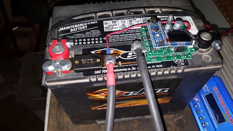
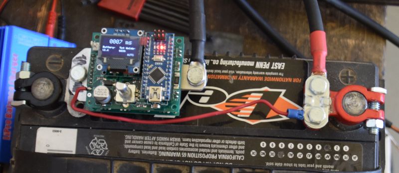
DIY Arduino timed spot-welder, FET-switched, adj. pulse

It's made with these:

http://www.ebay.co.uk/itm/171007548108?_trksid=p2060353.m2749.l2649&var=470239617285&ssPageName=STRK%3AMEBIDX%3AIT

listing says copper.

I've just ordered some 5mm diam soft copper wire so hoping that might be better...
 
I reckon the probes are the issue. I use 6mm pure copper rod to make the electrodes. For the cable i use 4 awg silicon coated car audio cable. Easy to get from any car shop. I crimp and solder it all together then add heatshrink.
 
Thanks Quokka - I'll try the pure copper probes when the wire arrives.
I've used 10AWG for the probe and battery wiring. Is it worth me upping that to 4AWG? I haven't noticed anything getting hot while firing the welder but I haven't used it for any length of time.
 
Would anyone be able to suggest a 12v Battery suitable for welding .3 Pure Nickel? I can see from Quokka earlier post he's running two Batteries in Parallel and can weld .2 comfortably. is it reasonable to expect enough current from a single battery to successfully weld .3 nickel? would anyone have an ideal battery recommendation?? Cheers
 
Its very easy to program the chip. All the instructions on how to do it are on the instrucatables website. basibally you download arduino software, plug the arduino nanno in via mini usb and then just upload a file that you download from the instructables website.
 
I like this setup very much, no special stuff to program is where its at.
I did quickly scan the DIY website for the chip.

I soldered up my own one of advweb's DIY welder and still got it. I enjoyed soldering it up and welding my used a123 cans. I find its a little weak and I tried every setting. Could just be my transformer. I do not know why it is weak. Bought my reel of strips from Fastech.com

I will rescan the links but whats the all-in cost for doing something like this, without the outsourced PCB?
Adruino + Parts

I must of missed it, or cant find it.
 
spinningmagnets said:
Flangefrog, I know you are a busy guy, but...do you feel we are close enough to order some PCB's to be ordered? and also publish a parts list?

I would like to get the ball rolling and order a batch of parts to make ten units. I'd like all the "open source" info published so anyone can go their own route, but I also want to take the next step and make a parts kit, and also a few finished spot-welders made available. If enough parts are ordered at the same time, the price per unit goes down. I'd like to spend some money to make this happen. I am certain that I can break even on a mass buy and distribution of kits, whether in parts or as a finished unit.

If this has a glaring error in design, we need to know now...if it is the best possible design from a bang-for-buck perspective, I'd like to verify that ASAP. Help me to make this happen...
I've been working on this circuit for this past year or so - been through a couple of revisions and learned quite a bit along the way. A couple of suggestions for improvements of this unit:

1) From the schematics on instructables there doesn't seem to be any gate resistors for the FETS. Riba used 82 ohms as I remember, then tesseract came along and recommended much lower value. It is generally accepted as good practice to fit them - a larger value slows things down for better stability. Without, you will get fast switching, but potentially unstable operation.

2) Insufficient decoupling capacitance. There is a .1uf ceramic with a 1uf electrolytic capacitor on the board. A builder on here has reported his MCU tripping out after fitting the schottky flyback diode. I suspect this is the reason - the function of decoupling capacitor is to absorb any fluctuation on the power rail (5 Volts). The ceramic handles high frequencies, the electrolytic handles low frequency ones. Also, these capacitors supply the fets with current to drive those
FET gates when firing a weld. It is good that there are four dual 3A FET driver chips, but I suspect that they are unable to supply all of their potential current due to the minimal capacitance on the board. I ended up using a single 6A driver with a copper pour on the board, 5 of 10uf electrolytics, 3 of .1uf ceramics and (shortly) a 1uf PET film cap (=low ESR).

If the designer could be persuaded to address these issues, then with flangefrog's code upgrade too, folks would have access to a pretty decent design I think.
 
Finished building mine up a few weeks ago, only tried it with 0.15mm Nickel. Works great! My mechanical design needs some work.. mostly 3D printed, got a few brass parts machined by a friend. Right now there is too much slop in the mechanism that (tries to) keep the electrodes aligned, yet allow them to be sprung independently. Big thanks to KaeptnBalu and Flange Frog for their efforts... If anyone wants CAD files for the mechanical bits, I will post them. I have 2 spare blank PCBs for the first two people to PM me their address (preferably in North America)
pdarduinowelder.png
 
placed an order on tindie for a full unit. Cant wait to try it.
 
I also placed an order for this welder and just got it Saturday! I have not got a battery for it yet and would love a suggestion as to what battery I need to buy so I can use .15 pure nickel strips on my packs.
 
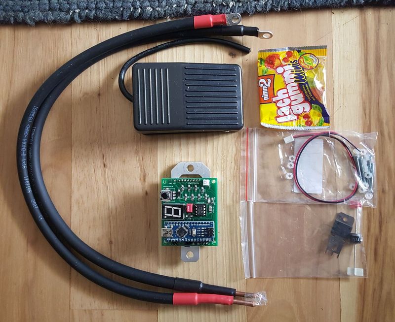
Spot-welder and two cables arrived today, well packaged. I will have to check Paypal to see when I paid in order to tell the shipping time. There was a delay, but...I rack that up to the recent popularity of this product, and the producer ramping up production. I only wished to say that I actually received what I paid for, and it looks well-made.
 
I am hoping you will do a good proper review SM, I look forward to reading it.
I think my issue with my unit from http://avdweb.nl/tech-tips/spot-welder.html was I was trying to weld 2 tabs together and onto the can (which isnt the right way to do it, just a beginners mistake on my part), I forget the thickness of the tabs off hand, but it was a great project, soldering the pcb and buying the parts, I enjoyed it. I plan to use it for my round of ~450 18650's, but as I said, I am interested in how this will perfrom, keep us updated SM.
 
I"m currently desgining a plastic enclosure for 3d printing, i allready have one version on thingiverse , but I'm working on a better one.
 
Received my kit today. Tracking is fair and customs held it for 4 days but all is good.
arduino%20welder.jpg
 
So far I built one battery pack 80 cells, and working on my second 80 cell pack. I'm also using 0.15 nickle strip.

On the first pack I built the welding cable I use was 8 gauge audio cable. The cable was getting very hot, I had to take many breaks to let them cool down. I also had to use power setting between 4.0 and 7.0 to get good welds, and zap each cell multiple times. I got it done but it wasn't easy. Took me 2 days to finish, did 40 cells one day and then 40 the next day because of the heat.

I decided to get new welding cables, this time I used 6 gauge copper welding cables, I just solder the copper probes to the copper wire. On my second battery pack, the cables only got warm when I did multiple cells one after the other, I also was using a power setting of 1.4, and was getting good welds, rarely had to do multiple welds to get the nickle to stick. Finished all 80 cells in one sitting about 2 hours.

The battery I am using is a fullriver 28 amp hour agm, its a small racing type battery (clone of the odyssey battery). It got the job done. After I finished I connected the fullriver to a charger and it quickly charged backed up, needed less than 3 amps to be back at full voltage.

I been using the xt90 connectors to connect the welder to my battery. For my situation it seems to work, but those needing more power might have to hardwired to battery. Overall I highly recommend this welder for those who need to build battery packs, its definitely has enough power for the job.


Welded .2mm to battery at 50MS without issue.
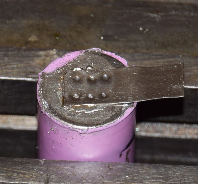
Welded 30 AWG fuse wire to battery at 0007MS
arduino%20fuse.jpg


fuse%20wire.JPG


[youtube]fm7UmFPuim0[/youtube]

I had an issue with Ver2. Marc said he had a batch of bad Mosfets. He offered me a refund or a new Ver3 when it comes out. I opted for Ver3 and waited 10 days till I got it. I had some software issue with Ver3 and that took me some time to figure it out waiting for reply from Marc. He replied and told me what to do but it wasn't very clear. My programmer son figured it out in a heartbeat. In the lines Marc says to add, you merely have to remove "//" before the 64 bit and put them in front of the 32 bit display. If anyone wants the SSD1306 file I can give it to you. The text was in the code, you just have to enable 32 bit and disable 64bit display.

When I stayed up till after midnight Marc replied immediately. He is a GREAT guy to work with.

I ordered 300anl fuses and holder which will be here tomorrow and a smaller power switch than what I had on hand. Marc said I don't really need the fuse with a car battery but I already ordered it on his online recommendation.

Ver3 is really nice as I didn't need the diodes nor the resistor to run off car battery. The LED is bigger as well as a longer knob. No need for jumper for auto pulse as it is programmed into software. Overall it is just easier to use.
 
I was playing with .2mm nickle. First good welds were at 50MS. THen I had to keep increasing time and was not getting good results. Was up to 180MS before got a good weld. Noticed buildup on tips so I filed them to a point and at 180MS blew through and tring to remove the tab it tore the tab leaving the tap piece still on battery. FIled again and set back to 50 and it looked good. So I guess to get reliable results you need to keep the tips clean and pointed.

A flat tip worked well with the fuse wire and made it easier to pin wire to battery.

Now that I decided to do a pack Tesla style with this fuse wire, I don't need the power of this welder now. In fact my china welder set at 25 did a good job with the fuse wire too!
 
Back
Top