
You are using an out of date browser. It may not display this or other websites correctly.
You should upgrade or use an alternative browser.
You should upgrade or use an alternative browser.
DIY Arduino timed spot-welder, FET-switched, adj. pulse
- Thread starter flangefrog
- Start date
hi all, I was again doing some research into this topic, came across this thread. I wanted to pass a little info I learned along the way, concerning the electrodes. Pure copper is NOT the best, as you have realized, you must keep them quite clean. There is an alloy made for this specific purpose (spot welding). It's mostly copper but has some burrilium (sp?) in it to keep it from corroding and going away as you use it. Also makes it harder. I don't actually remember the alloy, but learn about it looking up an old industrial stored energy spot welder I had purchased. Old as in it used vacuum tubes! As I am sure you all know, it is very important to keep the resistance in circuit down to a minimal, oxides drastically raise the resistance. Especially aluminum oxide. So be sure to keep the Aluminum parts very clean when assembling, maybe even use some very fine sand paper and silicon grease or something to keep that metal from getting oxides between connections. Also, BEWARE copper coated aluminum wire. It's crap and you don't want it. Remember, Aluminum Oxide is an insulator, not a conductor! Anyways, if you search, you can find copper alloy electrodes meant for spot welding if you look.
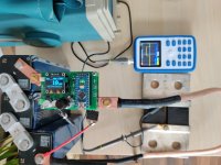
Malectrics V4, super capacitors 3000F 2.8V ESR 0.2mOhm
Shunt 1500A 75mV 0.5%
3800A Tektronix shows even a little more
https://imgur.com/a/a608RF0[/img
Shunt 1500A 75mV 0.5%
3800A Tektronix shows even a little more
https://imgur.com/a/a608RF0[/img
Attachments
Silvaticus
10 W
- Joined
- Jan 18, 2019
- Messages
- 66
How did you manage to trick the laws of physics and Ohm's law?
What is your total system resistance with open mosfets? You have three super capacitors in series.
This means that the total current source resistance (Ri) near 0.8mΩ.
The physical limit of your current source is at 800A according to the manufacturer's datasheet.
If I'm reading Ohm's Law correctly, it says that you need to achieve an total impendance/resistance (Ri + Rs +Rc + Rw) of 2.21mΩ to get 3.8kA current at a maximum voltage of 8.4V.
You go to forums and ask everyone for proof as a prosecutor ")
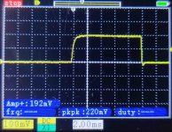
The total resistance during the measurement was about 2mΩ. Power switch(IRL40SC228), measured between terminal screws is a little less than 0.2 mΩ and now you have all the data for calculations. As far as I understand, you also have everything to repeat the experiment, including supercapacitors. Oscilloscopes are not very suitable for accurate measurements, but even taking into account such an error, it can be seen that the threshold for Malectrics at 3000A, which was discussed in the kWeld branch, has been passed.
The total resistance during the measurement was about 2mΩ. Power switch(IRL40SC228), measured between terminal screws is a little less than 0.2 mΩ and now you have all the data for calculations. As far as I understand, you also have everything to repeat the experiment, including supercapacitors. Oscilloscopes are not very suitable for accurate measurements, but even taking into account such an error, it can be seen that the threshold for Malectrics at 3000A, which was discussed in the kWeld branch, has been passed.
Silvaticus
10 W
- Joined
- Jan 18, 2019
- Messages
- 66
The question was quite simple. How is it possible to connect 3 super capacitors in series to get a current almost 5 times higher than the current from the manufacturer's datasheet. I do not have an oscilloscope and I am not able to take such measurements. In this regard, I asked how accurate they are. And most users do not take such measurements. They just enjoy welding.
Ohm's law allows you to get such a current, which is what I wrote at the end of the message.
In addition, it is not entirely clear to me personally from your message whether you measured the possible current from the voltage drop or took real current data with a full-fledged welding pulse. Because the potential of the current is just next to the level you specified. Because the current potential of the super capacitor is somewhere near 14kA. However, the manufacturer claims only 17% of the potential in the datasheet.
My questions are based on the desire to understand better, and not on some other ideas. They are actually noob, tk. in this area of education I have certain gaps. Perhaps that is why my questions seem very boring to you. Besides, I'm not sure if my calculations are correct.
With a full-fledged welding pulse, of course, such a current with three supercapacitors cannot be obtained.
This is almost a short circuit current for the power switch, the oscillogram shows a voltage drop across the 50μOhm shunt. I have not seen a datasheet for these capacitors, but I think I understand, you are looking at the Maximum current, it is not necessary if you do not feel sorry for these capacitors . Do not be lazy to search the net and you will find how people get about 8000A from six supercapacitors.
I have 9 such cans, I want to build a more powerful system for welding copper

This is almost a short circuit current for the power switch, the oscillogram shows a voltage drop across the 50μOhm shunt. I have not seen a datasheet for these capacitors, but I think I understand, you are looking at the Maximum current, it is not necessary if you do not feel sorry for these capacitors
. Do not be lazy to search the net and you will find how people get about 8000A from six supercapacitors.I have 9 such cans, I want to build a more powerful system for welding copper
Silvaticus
10 W
- Joined
- Jan 18, 2019
- Messages
- 66
Thanks for the more detailed answer. Now everything is clearing up.
Judging by the manufacturer's datasheets, if you manage to achieve a total resistance of no more than 2.33mΩ in your 3S3P assembly, then the maximum current (as it seems to me, it is the short-circuit current) that you can get will be at the level of 3.6kA. Although, perhaps I am in error considering the "maximum short-term current" in the datasheet to be equivalent to the short-circuit current. If so, then you are correct that a much higher current can be obtained in the first milliseconds. But this requires additional research and access to the oscilloscope.
If we neglect this assumption, then I think it is very difficult to get 8.0kA from six cells if you do not connect all of them in parallel. This will require (based on the manufacturer's published data on the maximum short-term current) at least a 3S7P assembly and a resistance no higher than 1.05mΩ.
Of course, if I operate with the correct formulas and have not made any mistakes in arithmetic operations.
Again, not true. I already received 3800A with three capacitors and one transistor assembly. How do I get 3600A with two transistor assembly in parallel and 3S3P capacitors ?
Again, do not look at the datasheet parameter (Max current) - this is not a short circuit current.
Or let's do it differently, what limits the discharge current of a bypassed supercapacitor besides its internal resistance and the resistance of the shunt?
Again, do not look at the datasheet parameter (Max current) - this is not a short circuit current.
Or let's do it differently, what limits the discharge current of a bypassed supercapacitor besides its internal resistance and the resistance of the shunt?
Silvaticus
10 W
- Joined
- Jan 18, 2019
- Messages
- 66
As far as I know, in a closed circuit, the current is the same in any of its sections. Therefore, the maximum achievable current depends on the total impedance of this section. We omit the voltage dependence, since we are considering the conditions for the same system. Am I interpreting your thoughts correctly?
If I understand you correctly, then we can say that at the beginning of the welding pulse, the current will tend to the short-circuit current. Later, this will lead to the stabilization of the current at a certain value. And this process in any case will obey Ohm's law.
If I understand you correctly, then we can say that at the beginning of the welding pulse, the current will tend to the short-circuit current. Later, this will lead to the stabilization of the current at a certain value. And this process in any case will obey Ohm's law.
Silvaticus
10 W
- Joined
- Jan 18, 2019
- Messages
- 66
Here's what I came across on the web on this issue.
«A simplified model of a capacitor is shown below.
It consists of:
Cp = parallel capacitance, or the bulk capacitance. In your case, the 1020uF capacitance.
Rp = parallel resistance, or, the leakage resistance. Typically in the tens of meg-ohm range for a properly formed aluminum electrolytic capacitor.
Ls = series inductance. This includes the inductance of internal plates, internal wiring, and leads. This could be hundreds of nH to tens of uH depending on the construction of the capacitor and lead length.
Rs = series resistance. Commonly called Equivalent Series Resistance (ESR) which has a frequency dependency. This includes the resistance of the capacitor structure, internal wiring, and external leads. This can be in the low milli-ohms to a few ohms depending on construction.
Rshort and Lshort are the resistance and inductance of your shorting conductor. These items are added to Rs and Ls.
The series inductances, Ls + Lshort, affects the rise time of short-circuit current.
The series resistance, Rs + Rshort, determines the short-circuit current (use Ohm's law). Rs & Rshort will change when you short the capacitor due to heating which is hard to quantify. Repeated high current shorts can damage the internal structure of the capacitor due to spot heating of the internal structure causing parametric changes.»


myxomop said:"BigMalectrics" ready
For welding copper with flux, six super capacitors were enough (copper 0.2mm tape + 2mm copper busbar, pulse 10 ms)
Nickel 0.2mm 2ms.
What is this compound, that you call a "flux" on the 3rd picture?
"welding copper with flux"
I looks like some sort of epoxy or silicone.
Next, on the 2nd picture, there is a device between the positive and the negative electrodes.
Is it a TVS diode?
If not a secret, what it is?
Thank you. :thumb:
So, this is actually some sort of a Silver Brazing paste, for example:
https://www.brazing.com/Products/silverBrazingAlloys
This means the process with this paste is Resistance (Silver) Spot Brazing, not Resistance Spot Welding.
They have 3 examples in the patent.
----------
BAg-1, Cd-45, EASY-FLO 45
Ag Cu Zn Cd
45 18 17 20
Since it contains Cadmium there is a recommended close replacement without Cadmium:
BAg-7, A-56T, SilverAlloy 560, Silvaloy 560, Safety Silv 56
Ag Cu Zn Sn
56 22 17 5
----------
----------
So, this is actually some sort of a Silver Brazing paste, for example:
https://www.brazing.com/Products/silverBrazingAlloys
This means the process with this paste is Resistance (Silver) Spot Brazing, not Resistance Spot Welding.
They have 3 examples in the patent.
----------
These are the modern names of this alloy:EXAMPLE 1 40 parts by weight of powdered Lag 45 silver solder, consisting of 45 percent Ag, 18 percent Cu, 20 percent Cd and 17 percent Zn; 60 parts by weight of soldering flux containing 50 percent rosin, 38 percent tallow and 12 percent sal ammoniac.
BAg-1, Cd-45, EASY-FLO 45
Ag Cu Zn Cd
45 18 17 20
Since it contains Cadmium there is a recommended close replacement without Cadmium:
BAg-7, A-56T, SilverAlloy 560, Silvaloy 560, Safety Silv 56
Ag Cu Zn Sn
56 22 17 5
----------
I can not find any modern equivalent of this alloy.EXAMPLE 2 50 parts by weighttof powdered Lag 12 Cd silver solder, consisting of 12 percent Ag, 45 percent-Cu, 7 percent Cd and 36 percent Zn;
50 parts by weight of soldering flux containing 45 percent rosin, 45 percent tallow and 10 percent sal ammoniac.
----------
This is just pure Silver, not an alloy.EXAMPLE 3 25 parts by weight of powdered silver; 75 parts by weight of soldering flux containing, 55 percent rosin, 30 percent tallow and 15 percent sal ammoniac.
Have you ever considered Tungsten or Molybdenum electrodes?
Commercial spot welders use this type of electrodes for welding copper, for example:
[youtube]_nWJQIrbI_g[/youtube]
Commercial spot welders use this type of electrodes for welding copper, for example:
Resistance Welding - Lap Weld 0.007" (0,2 mm) Copper Sheet
We used a 3/16” (5 mm) Tungsten electrode with a “rounded” tip. Welds are easily, and quickly performed, with great strength. We used 1AWG (40 mm^2) cables with this hand piece, to ensure we have as much current at the weld site as possible.
[youtube]_nWJQIrbI_g[/youtube]
Found this one:
"Battery flux Resistance welding copper spot copper flux"
https://www.aliexpress.com/item/1005002826064340.html
----------
Tungsten electrodes - I plan on testing this, since they are readily available in various rod diameters for TIG welding.
Molybdenum - I can only find 8 mm rods at the moment.
"Battery flux Resistance welding copper spot copper flux"
https://www.aliexpress.com/item/1005002826064340.html
Special flux for GuoXuan battery, Copper to copper spot welder, Current is needed 2000 A - 8000 A Above current The higher the current, the better the spot welding effect, Energy storage spot welder 8 About a millisecond Transformer Spot Welder General 60 About a millisecond, When buying flux, please make sure that your machine current can reach such a high current If not, it is impossible to spot weld copper, Please purchase carefully, Flux for disposable items do not accept refund, please see clearly in the purchase, thank you!
Product specifications:Copper flux
----------
Tungsten electrodes - I plan on testing this, since they are readily available in various rod diameters for TIG welding.
Molybdenum - I can only find 8 mm rods at the moment.
Similar threads
- Replies
- 0
- Views
- 950
- Replies
- 3
- Views
- 3,211