DIY handlebar display

spata

1 W
Joined
Jan 26, 2013
Messages
58
I have built a few home made handlebar displays, but they always looked.... well, a bit home made!
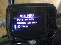
The problem was always with the housing, so I thought I would try and re-purpose something else. This is what I came up with;
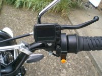
Handlebar_display_general.jpg
It is a cycle computer with the guts ripped out and a 128x64 OLED display and Arduino inserted instead.
Here are a few screen shots of just some of the modes I have programmed.
The bargraph at the left hand side is a fuel gauge and shows the battery remaining at any time.

View attachment 3
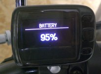
Handlebar_display_battery.jpg
Handlebar_display_main.jpg
I searched to see if I could find someone who could recommend a suitable enclosure but found nothing, so this topic is here for any others who are looking. The original cycle computer claimed to be waterproof, so it should be possible to make this one waterproof as well. The components are VERY tight but do fit, the really neat thing is that I managed to reuse the 3 switches so that you can have control of menu's etc or indeed other features of the bike if required (for example speed switch). In this first post I will only note the ‘golden nuggets’ of what I found.

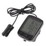
- The actual cycle computer that I used was an SD-563A by Sunding, size (5.5cm x 4cm x 1.8cm).
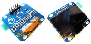
- The display I used was a 1.3" SPI Serial 128X64 OLED, size was 32.0MM * 35.5MM * 4.1MM.
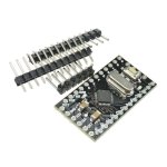
- I used an Arduino mini pro. I had to unsolder and remove the reset switch, as there was not enough room for it and I also removed the onboard LED(s) so that there is no light interference.
- Communication is via i2c, and I also wired the serial lines for datalogging and code download.
- I used U8Glib library for the Arduino code to run the 128X64 display.
- I used i2c_Anything library to get data to and from the Arduino (this allows you to send different data types int, float, bytes, etc between Arduinos very easily).
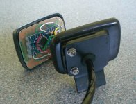
Here is a picture of the inside of the unit showing the Arduino, as you can see space is tight.
Handlebar_display_assembly.jpg
If anyone is interested or wants more details then let me know and I can elaborate with more detail.

- Spata
 
Definitely interested; are you willing to post the code? I've never messed with arduino but tried playing a bit with the STM32 Circle v1 (didn't get very far, was planning on a whole-bike monitoring/control system; started a thread on Ladyada's forums years back in hopes of help but never got anywhere).

Someday I'd like to get back into that (but I R not a programmer :oops: I might be able to eventually figure out and modify something else to do what I want but doing it from scratch....probably not).

FWIW, I already have a few little display screens from various "toys" and such, that could probably be repurposed for this type of thing. Would still need to get an arduino....
 
Very cool. Nice re-purposing of the enclosure.
 
I'm also interested. How about additional features such as speed and distance using a external wheel pickup
and a cruise function would be nice also. I currently have several displays that could be replaced by a
single one.

Thanks Joe
 
I built the display to use on this bike. I guess I should point out that in my case I have a network of 3 Arduinos all communicating via i2c. So in answer to Amberwolf my code is probably not the place to start as it distributed over the 3 processors and very specific to my use.

Joe, I do have speed, distance and a whole load of other functions incorporated into my Arduinos and output on the display, the 3 buttons on the front of the cycle computer are used to select which of the menus/menu items I want to display. For me the important bit is to keep the functions separate where at all possible. These processors are amazing, but pretty low in terms of memory. So the processor in my display is ONLY responsible for the display function, all the other data is sent to it via the i2c bus. This means that you only have 4 communication wires (2 for i2c + power and ground) regardless of what other functions you want to add. It also means that the cable to the handlebars remains thin, I have the other Arduinos tucked away under the bodywork, where it is easier to hind the inevitable mess of wires.

As to cost, I have just found the items on ebay and they came to £13.26 including p&p (£10.49 if I use slightly different sized parts) - so hardly expensive.

Here are the links:
- Cycle Computer - £4.01
- 128X64 OLED display - £8.26 (different versions available for £5.49)
- Arduino Pro mini - £0.99

Plus pictures of the bits:

Cycle computer.jpg
128 x 64 OLED display.jpg
Arduino_Pro_Mini.jpg
-Spata
 
Nice job there. I've wanted to build something but the housing is always the problem. Perhaps something 3D printed and sealed would be good. How visible are the OLEDs in sunlight?

For those not actually familiar with Arduino, it has grown to be such a popular item (unlike a lot of other boards) that there's a huge collection of code out there to use as a starting point, and many places like forums to get help and find others doing similar projects. Arduino was designed for artists, not programmers, so it tends to be simpler than many platforms, and documented at a lower level. There are many different boards available so finding something small is much easier, and moving from one board to another is also often trivial or at least not too difficult.
 
Great to see that you've posted up info this, I love how compact you've managed to get it. :D

I've used these little OLED displays for a few things attached to rasperry pis, and have been thinking about using a couple to show voltage/current/temp on the dash of my motorbike project, I'll need to read up on arduino first though as i've never used one.

Just wondering, how do you find the readability of the display while moving?
I found that the low PWM/update frequency of the display makes them look kinda blury (ghosting?) if they're moving much. (Though the one I use is I2C not the SPI one so you may not have the issue)
 
I have not found the image too blurry - but I deliberately only update on a 1 second time slice, this corresponds to my datalogging rate and I find that if you update these too frequently they get difficult to read, that may have been the trouble you had.

To be honest I would probably not use one of these as my primary display, I have a speedo for that. The idea of this display is so that you can have a very small and discreet method of checking status within your system. Having said that the display, especially if you only display one item at a time, is very readable (for example the battery image I posted). I also have limits set for my display items and I can highlight them if they go out of limits, that way they can be used more like idiot lights. The fonts, size, type etc are all programmable and a large variety are available in the U8G8Lib library. One bit of advice is try and limit yourself to 2 fonts, each one uses up a fair amount of memory on the Arduino and it took me a while to find that one!

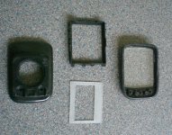
Here is a picture of the case, the bit of white plastic is something I made to convert the new screen to the cycle computer bezel (top most black bit).
I did think of 3D printing one, but I think if I was going that route I would print an entire bezel, but still use the original outer case.
Case_components.jpg
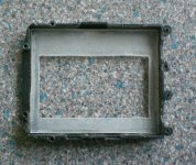
This is the white plastic converter mounted in the bezel.
Bezel_reducer.jpg
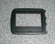
Then I painted it so that it all matched.
Bezel_painted.jpg
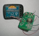
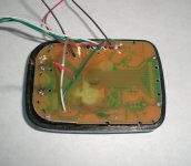
Here you can see the screen mounted onto the converter and glued into the bezel, you can also see the wiring to the stripped bare PCB from the cycle computer. You can hopefully see that I drilled some holes in the PCB to allow the wires to pass through and also see how to connect to the switch pads
Screen_Assembly.jpg
Then you screw the PCB down with the screws removed when it was disassembled.
PCB_screwed_on.jpg
This final shot shows how the Arduino was glued onto the PCB and hopefully you can see some of the wiring detail.

- Spata
 
spata said:
... that way they can be used more like idiot lights.
That is sort of what I was planning.

As I don't need an oil pressure light/neutral light I was thinking of squeezing the display in there.
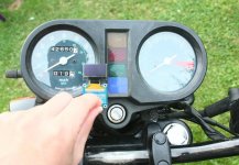
I'll have speed from the origional speedo and might see if I can modify the tachometer to display current, which leaves voltage/temp/cell status for the OLED.

display.jpg

I shall have a go at reducing the update rate an see if that makes it more readable.
 
That looks like it will fit in there nicely, if you take out the oil pressure and neutral - I am guessing the middle 2 idiot lights - you might be able to fit a bigger screen. The U8Glib supports screen rotation no problem so you can have the screen portrait or landscape.

- Spata
 
FWIW - the Arduino pwm outputs are just the thing to drive RC servos, if you want to repurpose the dial gauges for something else (volts, amps or amp-hours)
The tiny RC servos basically have a 180degree sweep and cost ~ $2 each (£1.5) (hobbyking)
I have such an analogue display on a partly built ebike & it looks & behaves very well...
BTW the display above looks fantastic - great job! I've not seen the little oled displays before, looks just the job!
 
Any chance you can repost a link to the photos, all the links appear to be dead :(
 
amberwolf said:
Regarding the pictures:
viewtopic.php?f=2&t=82335
I am guessing, since the pictures are still missing that they got lost when the server 'hiccupped'. I have re-uploaded all of my images, so have hopefully restored as much of the thread as I can.

- Spata
 
Back
Top