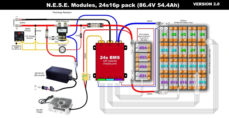
Do I need diodes with this layout?

TommyCat said:
If you don't mind me saying, I'd double check the converter's circuit breaker size. (Seems way too big.)

The PowerVelocity controller is capable of being programmed to a max of 200A battery Amps. He uses very large MOSFETs in his controllers. Being conservative, I plan to program it to use no more than 75A.

TommyCat said:
And the use of a Zener diode in the pre-charge circuit?

Yes. What is the question?
 
TommyCat said:
If you don't mind me saying, I'd double check the converter's circuit breaker size. (Seems way too big.)

Talking about the CONVERTER or buck transformer here... I'm thinking that on the supply input side the amp draw will be a lot less due to the higher voltage used. Odds are probably low for a total short, but with the smaller 16 gauge input wires. 50 amps seems high.

TommyCat said:
And the use of a Zener diode in the pre-charge circuit?

Yes. What is your question?

Just a rookie when it comes to electronics... But doesn't a Zener diode pass current in both directions? Was wondering if your key provided power would be on all the time with power leaking thru the pre-charge resistors/Zener diode from main battery power.

Perhaps the particulars of the diode your ordering would help me.

Another gem from your pre-charge link... http://www.zeva.com.au/index.php?product=110
 
TommyCat said:
Another gem from your pre-charge link... http://www.zeva.com.au/index.php?product=110

Yes I was aware of this item. But it requires 12Vdc switched circuit. As it is, the PowerVelocity controller I am considering has an extra-cost option of 12V out which I may opt for even if left unused. Some controllers don't offer this btw. As it is, I am not going to introduce a contactor into the equation as I originally thought as I have been assured by PowerVelocity that the controller uses a minuscule amount of current when switched off (even when connected directly to the battery).
 
TommyCat said:
Version 2.0

Save the contactor... added switch fuse.


maIagYi.jpg

Is there a need to discharge through BMS? You could save some space using bms that is rated for your max charging current. The way I do it, is i take battery output and connect it to controller and positive going through contactor as you have. Then one small gauge wire off the battery negative goes to bms input and from bms output goes to contactor coil. If battery falls lower set threshold, bms cuts out contactor. This way bms does not limit your discharge rate, you control it with controller. You don't have aditional bms looses. Its a win win scenario.
 
agniusm said:
The way I do it, is i take battery output and connect it to controller and positive going through contactor as you have. Then one small gauge wire off the battery negative goes to bms input and from bms output goes to contactor coil. If battery falls lower set threshold, bms cuts out contactor. This way bms does not limit your discharge rate, you control it with controller. You don't have aditional bms losses. Its a win-win scenario.

I tend to agree. Most modern BMS's tend to have built-in current switches. Which is why I am considering forgoing the traditional "contactor" pattern. But I might change my mind too...
 
TommyCat said:
Version 2.0. Save the contactor... added switch fuse.

So after consulting with a few experts in the field of electric golf carts and fork lifts, they are all aghast at the idea of running a system without a contactor. Given that, I went back to the literal drawing board and now have come up with the following layout.

New this version 5b:

1.) Ditched the BMS and replaced it with (20) BlocBalancers, one per parallel "block"
2.) Re-introduced a contactor to the main power to the controller, powered by the optional 12v switched circuit from the controller
3.) Added ZEVA smart precharger circuit to the contactor
4.) gave up on the Curtis DC-DC converter as it cannot be sourced in the USA as a switched version. Replaced with a converter from electriccarpartscompany.com instead

32351223798_756c94131c_o_d.jpg


Michael

PowerVelocity 20kW Controller + QS273 + (20) BabyBlocs + (80) 5p NESE Modules: 20s20p pack (72V 72Ah)
 
MJSfoto1956 said:
So after consulting with a few experts in the field of electric golf carts and fork lifts, they are all aghast at the idea of running a system without a contactor.
That's primarily because those typically use a brushed motor, which if the controller fails generally leaves the system stuck at full power, with no way to shut it off other than disconnecting the battery from it.

A contactor makes that relatively easy, since trying to yank off battery wires or pull plugs out is tough while you're going full tilt uncontrollably. ;)

Though many of the people running brushed motor systems don't seem to know it, a brushless motor system does not have this failure mode. There are other reasons for a contactor, but runaway isn't one of them.
 
How do those balancers work? I think you need bms as per your previous illustration.
OK, i have read it. So, you have to do the math if that balancer will be able to keep up with your charger, otherwise you will overcharge. There is no need for large disipating resistor if you use new branded and good quality cells. If they are not in balance it will take longer first charge and then it should be good.
Also the will not have protection agains overdischarge. So one of your cells might drop below safe limit and the you will wreck that modules group.
 
… regarding the pre-charge system. Does the switched controller's 12 vdc output get it's primary voltage from B+ (+72v) which is waiting to be switched on? Or from the ignition "on" wire (Vcc) which to me would seem unlikely.
 
TommyCat said:
… regarding the pre-charge system. Does the switched controller's 12 vdc output get it's primary voltage from B+ (+72v) which is waiting to be switched on? Or from the ignition "on" wire (Vcc) which to me would seem unlikely.

Not quite. The PowerVelocity controller has an optional (i.e. extra cost) switched 10A 12VDC external power supply, which I propose here to power the ZEVA unit.

M
 
agniusm said:
Also they will not have protection agains overdischarge. So one of your cells might drop below safe limit and the you will wreck that modules group.

Not sure how "one of my cells might drop below safe limit" would ever happen.
Each group is a 20p -- they will self balance.
Unless you mean "one of my 20p groups might drop below safe limit". I suppose that would be possible.

M
 
agniusm said:
So, you have to do the math if that balancer will be able to keep up with your charger, otherwise you will overcharge.

The BlocBalancers are by default set to 4.15V before tripping. I may even opt to order them custom programmed to 4.1V max -- need to think on that a bit. Another thing I plan on doing is to also order the battery charger set from the factory to limit voltage to 82V max. I have no plans at all ever charging the cells to 4.2V.
 
MJSfoto1956 said:
The PowerVelocity controller has an optional (i.e. extra cost) switched 10A 12VDC external power supply, which I propose here to power the ZEVA unit.

As you already have a switched external 12vdc supply, why not use it? :wink:
 
TommyCat said:
As you already have a switched external 12vdc supply, why not use it? :wink:

Good point! LOL!

(actually there is a reason I will likely use the controller -- it comes down to the fact that I will be doing the project in "phases" with the 12V subsystem probably going in last)
 
MJSfoto1956 said:
agniusm said:
So, you have to do the math if that balancer will be able to keep up with your charger, otherwise you will overcharge.

The BlocBalancers are by default set to 4.15V before tripping. I may even opt to order them custom programmed to 4.1V max -- need to think on that a bit. Another thing I plan on doing is to also order the battery charger set from the factory to limit voltage to 82V max. I have no plans at all ever charging the cells to 4.2V.

Even if its set at 4.15v, it will drain cells when that voltage is reached. But what happens if charging power per cell exedes drain power of the balancer? It will overcharge as the charger will be switched on. Bms would disconnect charging, then drain cells and repeat the cycle. There is a risk here with bigger chargers.
 
Back
Top