Eastwood’s first battery build

So it’s been a while since I’ve updated this thread. I’m still working on the battery and and will post more pictures once I get finished.

So I have a question as far as using a fuse or not. Since I’m using a BMS with overcurrent protection would I still need to use a fuse? I’m leaning toward not using one unless you all think it would be unsafe. The BMS will NOT be bypassed so I would think that would be enough protection, but please correct me if I’m wrong?!?
Funny, @Dui ni shuo de dui and I just argued the pros and cons of that in a different thread.
 
Personally, I'd always use a fuse on the actual battery output, as close to the casing as possible (inside right at the cell block output is better but less accessible for repair), just because there are situations in which a wiring fault (crash, etc) could short circuit the battery itself, and if the BMS FETs failed stuck on for any reason (which you won't know until it tries to turn them off and can't), it couldn't do anything about such a short, and you could end up with a fire in the wiring even if it doesn't hurt the cells, etc.

The fuse can be much higher current than you will ever actually use in the system, as long as it's rated for the system voltage *in DC Volts* (not just AC) to be guaranteed to break the circuit. (it *might* still break the circuit if it's not rated for it, but it isn't guaranteed, and if it's only AC rated it is sized to expect zero voltage many times a second where it may break an arc).


There are several times over the decades I have not had a fuse in some power supply (battery, PSU, etc) output and some wiring fault or miswire occured that nearly instantly began smoking the wiring insulation, or actually setting it on fire. Once there was a breaker but it was really installed as a switch, and it did pop, but not until after the whole wiring harness that included the wires that shorted was melted into a single mass of plastic and metal. :(

None of these was a really high current source, or high voltage, they were all less than 24v, most were "12v" (13-14v actual) systems. I don't really like to imagine the heat and fire potential if they'd been something like my EIG traction packs. :(


There are certain battery configurations where fuses *between sections* might even be desirable, to avoid "plasmaboy" scenarios. Electric Vehicle Discussion List - How Plasma Boy Got His Name


Disadvantages to a fuse are more interconnects so more possible failure points, a very slight voltage drop across the fuse under load, etc.
 
So it’s been a while since I’ve updated this thread. I’m still working on the battery and and will post more pictures once I get finished.

So I have a question as far as using a fuse or not. Since I’m using a BMS with overcurrent protection would I still need to use a fuse? I’m leaning toward not using one unless you all think it would be unsafe. The BMS will NOT be bypassed so I would think that would be enough protection, but please correct me if I’m wrong?!?
Yes a fuse is absolutely necessary.
You cannot rely on anything else. If something goes very wrong there WILL be a fuse somewhere no matter what. Either it will be your controller, your BMS, your power wiring or, worse, your battery, but something will burn for sure in case of short circuit.
The BMS can go wrong and if it goes wrong it is possible that it fails closed, which would allow current to pass.

You want the stuff to burn to be something that has been designed for it and that you know will burn without damaging surrounding stuff. This is really something that cannot be skipped in a safe build, in my opinion.

If it is to be integrated inside the battery, make sure that the cells that are close to it are protected physically from damage for when the fuse will burn. If it's not convenient to put it inside the battery then you can also move it outside of the battery on the power wires, but the closer to the battery the better (in case there's a short on the main power lines).
 
Last edited:
Funny, @Dui ni shuo de dui and I just argued the pros and cons of that in a different thread.

Thank you! Yes that thread was very useful.

Personally, I'd always use a fuse on the actual battery output, as close to the casing as possible (inside right at the cell block output is better but less accessible for repair), just because there are situations in which a wiring fault (crash, etc) could short circuit the battery itself, and if the BMS FETs failed stuck on for any reason (which you won't know until it tries to turn them off and can't), it couldn't do anything about such a short, and you could end up with a fire in the wiring even if it doesn't hurt the cells, etc.

The fuse can be much higher current than you will ever actually use in the system, as long as it's rated for the system voltage *in DC Volts* (not just AC) to be guaranteed to break the circuit. (it *might* still break the circuit if it's not rated for it, but it isn't guaranteed, and if it's only AC rated it is sized to expect zero voltage many times a second where it may break an arc).


There are several times over the decades I have not had a fuse in some power supply (battery, PSU, etc) output and some wiring fault or miswire occured that nearly instantly began smoking the wiring insulation, or actually setting it on fire. Once there was a breaker but it was really installed as a switch, and it did pop, but not until after the whole wiring harness that included the wires that shorted was melted into a single mass of plastic and metal. :(

None of these was a really high current source, or high voltage, they were all less than 24v, most were "12v" (13-14v actual) systems. I don't really like to imagine the heat and fire potential if they'd been something like my EIG traction packs. :(


There are certain battery configurations where fuses *between sections* might even be desirable, to avoid "plasmaboy" scenarios. Electric Vehicle Discussion List - How Plasma Boy Got His Name


Disadvantages to a fuse are more interconnects so more possible failure points, a very slight voltage drop across the fuse under load, etc.

Thank you for all the useful information!

Yes a fuse is absolutely necessary.
You cannot rely on anything else. If something goes very wrong there WILL be a fuse somewhere no matter what. Either it will be your controller, your BMS, your power wiring or, worse, your battery, but something will burn for sure in case of short circuit.
The BMS can go wrong and if it goes wrong it is possible that it fails closed, which would allow current to pass.

You want the stuff to burn to be something that has been designed for it and that you know will burn without damaging surrounding stuff. This is really something that cannot be skipped in a safe build, in my opinion.

If it is to be integrated inside the battery, make sure that the cells that are close to it are protected physically from damage for when the fuse will burn. If it's not convenient to put it inside the battery then you can also move it outside of the battery on the power wires, but the closer to the battery the better (in case there's a short on the main power lines).

Thanks!


OK, all 3 of you have talked me into using a fuse. makes complete sense that a fuse is always necessary. As far as putting it inside the battery, there is no extra space.
For the location of the fuse., it will have to be on the output side of the coil contractor, or connected straight to the controller. I don’t have a lot of options because of space. That’s good to know that the fuse is better to use inside the battery, makes sense because any wires before the fuse would just burn. Then those wires would become your fuse lol


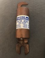
Have a used EV fuse that’s rated for 125VDC - 400amp. I could consider a larger fuse, since my controller can technically output 500amps.
IMG_0301.jpeg
 
Last edited:
Does your BMS have a UART port on the side like this image below
I think it does, but not 100% sure.
The ant BMS has a screen and I think it sends data from and to it via UART.
 
Had fun reading this thread, good stuff in here. I have spent a fair amount of time researching and while I appreciate your very real fear of catastrophic battery failures and therefore very necessary provisions to reduce the risk of said failures…there are some aspects of your build that I find completely overkill and possibly even detrimental to your goals. For that reason I wrote this reply.

My main point is concerning the busbars and the bolted interconnects you are using between the stacks. 1mm copper busbars…I of course have no data to back this up but I feel like the difference in overall pack resistance compared to say 0.2mm or 0.3mm copper is, while nonzero, negligible when compared to the added weight. I mean after all you are trying to reduce resistance so you have less voltage sag which would result in more power and efficiency…but every gram you have to accelerate takes more power and effects energy consumption.

Nothing wrong with bolted connections. I, in the past, have used the nickel copper sandwich for interconnects. I get the busbars made such that there is extra length to be bent and folded over such that I can spot weld the interconnects together. Not possible with 1mm copper, but is possible with 0.2mm, maybe even with 0.3mm copper. 1/0 cable is overkill if that was your main discharge cable, let alone using three in parallel to make interconnections. Again, the added weight and space that those cables are taking up which could be more battery cells instead, just doesn’t seem like a worthy tradeoff to me. I have a pack that discharges 500amps. 21S17p molicel p42a. I use one 2awg cable soldered to main positive and negative. 0.2mm copper for all the busbars. Voltage sag is not an issue. 29.4amp max draw per cell at peak amperage which is only for probably 2-3 seconds max, this is no problem for the busbars and cables im using. The wires dont even get warm. The pack has never even seen 40 degrees C.

Love your attention to detail and wanting to make things overkill, I just think you may have taken it too far past overkill to where it is hurting more than helping. Again, I have no measurements to back up my claims, just experience using a lot less and getting great results. You are building an amazing battery all things aside and I agree with 99% of the steps you are taking to build a safe and reliable battery. There’s my 2 cents!
 
Back
Top