Eaton APR48-3G 1.8kW Light Compact Charger PSU

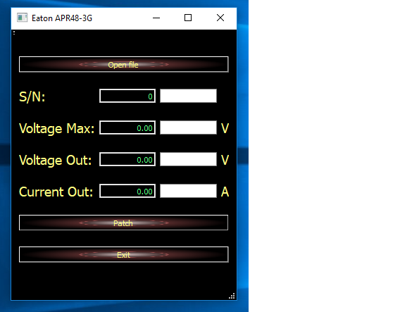
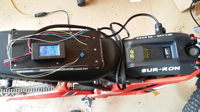
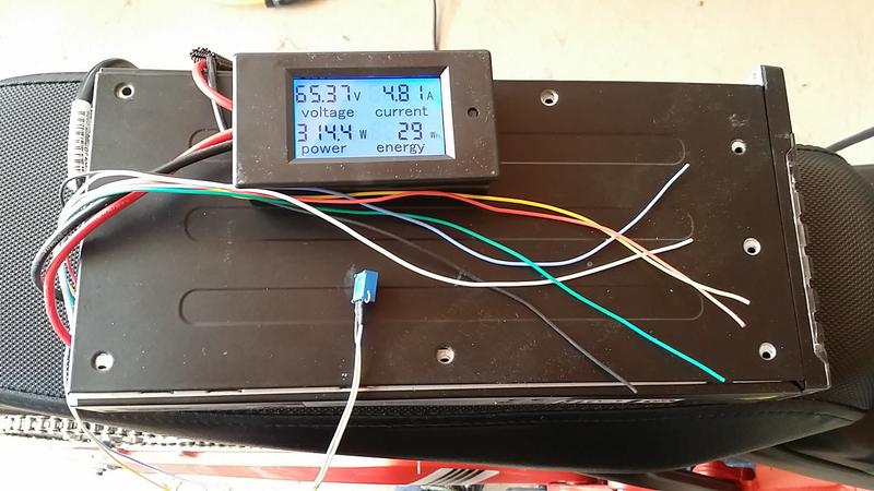
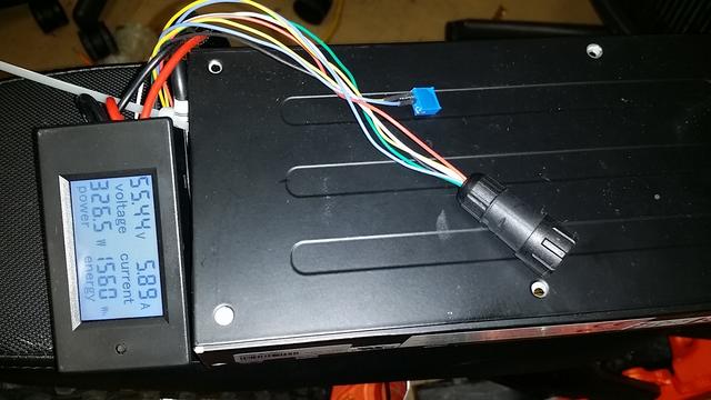
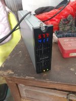
Mate, that's the over-volt limit, you can't program it higher than 58V. You'll need to cut the trace and solder the resistor on it if you want to go above 58V or below 43V.

You can set it higher but it won't do anything.

I'ts all documented in this and the Russian thread :cry:. No offense but it wouldn't hurt if you played with the settings a bit instead of asking advice for every little thing.

As you might have guessed this thread is pretty dead, it's all been said. There is nothing new to discuss really.
 
Very sorry, I just read through the thread when looking for the firmware file and didn't see anything about this value in the Eaton.exe patch tool.

And LOL, you think I should play with the settings a bit, are you crazy??????? Well you saw what I did when I played with the settings the last time I thought I broke or what we call "bricked" here in USA, my Eaton Power supply and even had to buy another one. :lol: Which was a waste of money because I didn't need it obviously. So yes I am playing it safe here with the questions.

However, Max Voltage still doesn't make sense to me and I'm new to all of this programming.

Why do you have a voltage Max when you have a voltage out? I set voltage out to 53 volts and it works fine.

I would think you only need voltage out and current out? I've set CC-CV manual power supplies and there is a pot for each of these. Never saw reference to a third value called voltage MAX.

So call me stupid but I just can't be sure what this Voltage Max value is. Does this have to do with maintaining amps in the CC and raising voltage to do just that? Is that value simply just there to remind you that you can't go above 58 volts and you can change this value also?

The other thing is I can program and change this max voltage with the Eaton patch software, so I just programmed my voltage Max from 58 to 65. I didn't upload this to my power supply but based on what you are saying I just raised my max voltage limit.

SGVQlcz.png
 
AFAIK that voltage MAX was included because people were asking for it to try to set the limit higher, but it ended up not working so there is no point in messing with it.
 
Thanks, Here is what I plan on doing with my Eaton and why I wanted to program it. I needed to get this working quickly as a 2nd charger for my Sur-Ron bike.

I want to charge my Sur-Ron to 66 volts. The Eaton can not reach 66 volts so I will use a 12 volt mean well power (4 amp) supply with it in series.

I may have to make a separate post for this but when using the APR48-3G with the 4 amp power supply do I need to use any diodes when connecting them in series?

The reason I ask is because they recommend to use diodes across the + and - voltage out on the individual power supplies to stop back feeding when using multiple power supplies in series. Back feeding is when one power supply starts before another and it will back feed voltage/current into the other when using multiple power supplies in series.

The Eaton and the Mean well may both have this protection built in because they are built very well and t his may not be needed.

The other question I have is that do I need any diodes on the + or - terminals of the series connection of my power supplies. This would be necessary if I unplug power to my charger while still connected to my bike, and the bikes battery voltage back feeds into the Eaton and meanwell.


Thanks if anyone can answer any of these questions where I need diodes on using the Eaton and meanwell in series for 66 volt charger.

In the picture is the Eaton APR48-3G and a Meanwell LRS-50-12. I will use both of these in series for a 66 volt 4 amp charger. In the bottom picture of the LRS-50-12 you can actually see a diode still installed between the + and - output of the power supply as I had this used for my hybrid car battery charger.

cok2obL.jpg


o1zFB5C.jpg
 
You can do the resistor mod and get up to 68V no problem. I don't know why you would want to complicate things by adding another PSU in series.
 
I think you are correct :bigthumb: , I didn't realize the POT mod actually allowed higher voltages than 58.

This would surely make my life much much easier to be able to adjust the voltage with the POT to 66 and then program it for 4 amps CC. I could also maybe fine tune the charge because sometimes I don't want to charge as high as 66 all the time.
 
Very nice, I got my voltage to 66 volts.

It took 6.5K ohm on my POT to go from 53 volts to 66 volts.

I would always make sure you start at 0 ohm because I don't know what would happen if my 100K pot started at 100K, would it possibly send the voltage so high it would damage the power supply??

I'll post the actual results of charging my bike at 5 amps and 66 volts with this setup when I get around to making a harness/connector for the battery. Very nice if it actually works.

Also waiting on my amp/volt gauge that someone else used in an earlier post. This way I can easily monitor the charging.
https://www.ebay.com/itm/122029089742

80Yvj6W.png
 
Nice to see it working. :thumb:

As it has been said here before though, if you cut the trace the highest it will go is 68V so nothing to worry about.
 
Very nice, everything is working. I need to secure everything better so it is just setup as a test.

I left the 6 colored silicone wires to hook to my programming. I need to make some kind of connector or possibly just leave it permanently connected to my programmer.

Best to use a 10K Pot. I'm using a 100K pot and while it works it takes very small turns to change volts. It was also impossible for me to set it to 65.6 volts for a 4.1 Volts per cell charge. I could set it to 66.4 or 67.0 volts. I assume this is because the 100K post is too sensitive.

I programmed the Eaton for 5 amps CC.

With the Display gauge, you can easily set the voltage by just unplugging the charger from your bike and have the power supply powered. This is nice because I am always adjusting my charge voltage to not keep my battery fully charged.

ddIdqbx.jpg


Fn1fRmb.jpg


n4URVjh.jpg
 
Please help me! I cannot adjust the voltage to below 54 volts but can only adjust from 54 volts to more than 60 volts. I want to adjust the voltage at 48 volts. I am using 10K variable resistor
 
Andykool1810 said:
Please help me! I cannot adjust the voltage to below 54 volts but can only adjust from 54 volts to more than 60 volts. I want to adjust the voltage at 48 volts. I am using 10K variable resistor

You need to program it to go below 49 volts, you can only increase voltage with the resistor or pot.

Think about it, normally the copper line you cut to put on the resistor has 0 ohm resistance before cutting and that would give you 49 volts. Adding resistance with the pot/resistor increases the voltage higher.

How could you possibly go lower by increasing resistance?
 
By cutting it and lowering the resistance you increase the voltage and by adding more resistance you decrease the voltage.

There is a limit though as to how much you can change it with that method, you'll need to reprogram it to a lower voltage.
In the first page of this thread it is explained how to do it and where to buy it.
 
eee291 said:
By cutting it and lowering the resistance you increase the voltage and by adding more resistance you decrease the voltage.

There is a limit though as to how much you can change it with that method, you'll need to reprogram it to a lower voltage.
In the first page of this thread it is explained how to do it and where to buy it.

OK, I'm missing something. Cutting a trace increases the resistance to effectively be infinite. It doesn't lower the resistance. Right?

I'm no electronics expert either, but it seems to me that if you added an On/Off dip switch in parallel with the newly added pot, you could effectively return trace and remove it at will, putting it back to its original (or near original) configuration.
 
The only way I see you can lower the resistance is by putting solder on the trace, the same you would do with a shunt. However since such little amps flow through that trace, it would be so minuscule how much you could possibly lower the resistance. Now of course this is assuming you are starting out with close to 0 ohm resistance of the uncut trace with no pot on it.

Of course if you turn the pot up to 10K Ohm resistance, and then decrease the pot to 1K ohm resistance you are decreasing the resistance and therefore lowering the voltage.

This is why I see no way you can lower the volts unless you program it.

Just remember if you use the page 1 of this thread programmer, you will get errors but it should still work. Like if you verify chip signature, you will get an error at first then it will say your chip signature is 0x298818 or something like that for example. If the programmer doesn't really work, like you messed up the wiring, you will get multiple errors and not get any chip signature at the end.

This is what fooled me is that I thought mine wasn't working and then I started to hit write options in the programmer and erased my FLASH. Which wasn't a big deal anyway because we have the flash and EEProm files.
 
Added a 6 pin connector for my usb programmer. I had bought this 6 pin connector for my Max-E controller and never used it.


Probably easier to use the ribbon cable the USB programmer came with. The only issue with that is the wires can easily break and pull out of where you solder them to the power supply. Care must be taken once the ribbon cable is soldered to the power supply that you secure it to the power supply so there is no pulling on where the wire is soldered. I kept having issues and just used the 28 gauge silicone wire.


to52w2G.jpg


QkTLspT.jpg


I6SmsIV.jpg
 
Hello again! I have these for sale, if anyone is interested. I'll add pictures when I can. I have not personally tested these, but one buyer said that these are a bit noisier than newer versions. https://endless-sphere.com/forums/viewtopic.php?f=31&t=85677&p=1471853&hilit=Apr48#p1471853
 
notger said:
I wanna bring this up once again:

Any ideas or experience making a resistor-pot mod for changing the output Current ??
like the output voltage mod, just for current.

The reason for it would be to make a slow and fast charging switch to the Eaton

greets
Notger

Totally agree with that. It's a really convenient feature to preserve your battery lifetime while having the ability to charge quickly if needed. Re flashing with the phone is a good workaround but it should be possible to do it better.

Does anyone have an idea to make a pot or a switch mod for current adjustment ? Would be happy to try on my Eaton !
 
honya96 said:
Still no one knows how to limit current by HW?

current can be adjusted by hardware, 0 ~ 38A
 

Attachments

  • mmexport1583466466411.jpg
    mmexport1583466466411.jpg
    157.9 KB · Views: 1,737
  • mmexport1583466396086.jpg
    mmexport1583466396086.jpg
    83.1 KB · Views: 1,736
57.7V 41.1A(2371W)Worked for 30 minutes
 

Attachments

  • mmexport1584355964613.jpg
    mmexport1584355964613.jpg
    114.9 KB · Views: 1,639
Is this even a legit Eaton rectifier?
Could you snap a few pics from the pcb?

30 minutes isn't even that bad considering ~570w over spec.
 
Very exited with the mod you have done, it sounds awesome ! :bigthumb:

Could you explain how you did that ?
 
Back
Top