Ebike Battery Monitoring and Control System

Alan B said:
I'm on other projects right now. No progress here myself, though a fellow in Germany has been doing some work with this Intersil chip and we've corresponded a bit. As with all of these chips, getting them going is a bit of a project. Best of luck with your new pack.
Can you give me contact of that "fellow in Germany" ? Thanks!
Also eagle schematics and/or pcb would be mostly welcome - I don't use diptrace - have you tried designspark pcb - its free.
 
Well, it's been quite some time but I've picked up this project again a few weeks ago. As I was the one originally bringing up the Intersil chip, I thought I'd at least report my progress.

I've just ordered the revision 2 boards from OSH Park. 3 boards for US$20 shipped free world-wide is a bargain! Here are the top and bottom side renderings of the BMS node board. The PCB measures 42x50 mm, so 3.25 sq. in.
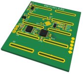
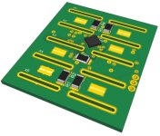
Top side.jpg Bottom side.jpg
My system is designed to work with the LiPo pouch cells you can get from HobbyKing (5000mAh). The board is designed for a 5S/2P configuration with the cells sitting on either side of the board. Like this:


The tabs of the cells go through the slots in the board and get soldered together. The complete assembly is designed to then slide into extruded aluminium box profile, ending up with a battery 5S/10Ah module of roughly 300x55x45 mm. I use two of these mounted to the down tube of my e-bike. The connections are + and -, and a comms connection for daisy chaining modules together in series.

The software and PCB are working and these rev 2 boards have the changes from testing of the rev 1 boards. U1 is the Intersil chip and U3 is the PIC24 micro. I haven't added all the costs but including the PCB it should come in at a shade over US$10, which is not bad.

The summary features are:
- 5-cells in series, either LiPo or LiFePo4, 1P of 2P
- Auto-balancing with every charge
- LVC and HVC alarms (via comms)
- One temperature sensor per side of 5 cell pack, plus PCB temp sensor
- Optically isolated serial communication for daisy-chaining to master module, which controls the charging process
- No shunt resistors, i.e. discharge current is not monitored
- Stand-by current of less than 5uA per cell

Hopefully, I'll have the rev 2 boards back from OSH Park in a couple of weeks and will be assembling and testing them.
 
Can you describe the extruded case your system fits? It sounds similar to what is used to house controllers....
 
jkbrigman said:
Can you describe the extruded case your system fits? It sounds similar to what is used to house controllers....

Nothing fancy. As long as it has minimum internal dimensions of 50 mm high (or 2") and 44 mm width (or 1 3/4") it will work. You could probably even use plastic rectangular gutter down pipe like this if it has the right dimensions.

rps2_122.jpg


I just search for "extruded box section", cut it to length and put plastic end caps on it. I don't have a picture to hand on this PC but it's a very simple assembly. You can feed the wires out at the end, through the caps, or up through the box section in the middle where the PCB sits.
 
parabellum said:
It can be tricky soldering in between cells like this but after that I would really hate to replace some dude cell in the middle. Overall idea is nice BTW. :)

Yes, pack surgery is tricky at the best of times. I always cycle test the individual cells a few times and measure the internal resistance to try and weed out duff cells before assembling a pack. So far, I've only had to do pack surgery once, and while it is tedious, it's not overly difficult. But, yes, there is a trade-off between minimizing module size and serviceability.
 
2moto said:
jkbrigman said:
You could probably even use plastic rectangular gutter down pipe like this if it has the right dimensions.
I originally used Polyvinyl rain gutter downspout for my batterycase (3x 4S1P 5Ah HK hardpack LiPo that you and most others use) but at 222Whr, the battery was *just* enough capacity for me (185lbs + 43lbs bike) and the 1000' climb up to my house the last 1/2 mile but I'd often find myself juiceless partially up the hill.

I ordered 3 more 4S packs to build a 12S2P 10Ah setup by slicing the top off the rain gutter then "folding" the resulting "U" channel over on itself so there was a seam down the sides toward the middle, the connecting end closed by folds, and the open end with two short sections that "fold"over each other. The squared shoulder of the "folded" ends keep them pretty well secured, but I put a piece of clear packing tape over it to keep it 100% secure. To charge, I take the tape off, unfold the ends, re-configure to 6S4P with the HXT connectors separated and charge with my iCharger 206 or 308. It's a bit of a pain but works for now:


I want to put a BMS (hence my interest in this project) and permanent case in there with an increase to 13S2P or 14S2P but all the case option seem non-optimal, although the mid-battery BMS board idea with cells on each side has me toying with leaving it 12S. There's not a lot of space in this frame, so I'm also contemplating finding a sheet metal brake and folding one up, but gawd I know that'll turn into a multi-weekend project :?

If anyone building custom batteries has found any interesting solutions for tight spaces, please let me know. Meanwhile, this rain gutter is really handy for quick and cheap battery cases while prototyping. A 10' stick is just $9 at Home Depot here in the 'States.

-=dave
 
Back
Top