Ebike Hub 3 phase wire melting issue

Supreme Kay

10 mW
Joined
Aug 29, 2016
Messages
32
Location
Tallahassee, Florida
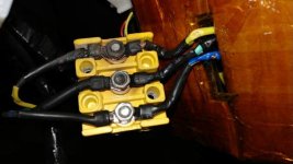
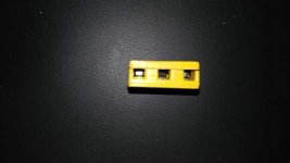
I am having a recurring issue, the 3 phase wire of my e-bike keep melting. I had them set up into a three wire block (see picture). I own a dual voltage e-bike 36v/48v e-bike (KT3 e-bike LCD) and my controller (KT36v/48v) is rated for 36v/48v 22 amp max current. As of now, I have a 36volt 11ah battery that has a BMS with 20 amp max discharge, I bought a 48v 10.5 ah battery a few days ago (the battery is still on the way). I am considering using Anderson power pole (from here:https://www.amazon.com/gp/product/B01HDZ91G8/ref=oh_aui_detailpage_o05_s00?ie=UTF8&psc=1) to connect the three phase wire of my e-bike hub motor to my controller hoping this will solve the wire melting issue I am having. I am not skilled with soldering, therefore I am looking into connector allowing to crimp wire to the connector. I am upgrading to a 48v battery and I am looking into solving this issue permanently because the 48-volt battery is going to generate more heat. According to the seller, the connector and housing of the Anderson Powerpole connector have a maximum operating voltage of 600 volts AC/DC and an operating temperature range of -4 to 221 degrees Fahrenheit.I would appreciate any opinion and suggestion that could help remedy my issue. My e-bike is my daily drive Thank for taking the time to respond to my post. I bought my motor from eBay from this seller: http://www.ebay.com/itm/322247604604?_trksid=p2057872.m2749.l2649&var=511147989362&ssPageName=STRK%3AMEBIDX%3AIT
I purchased the 500watt motor which has 35.5NM torque. Can please provide a link of connectors I could purchase to solve this issue?
 

Attachments

  • 20161227_064131__1482849856_98.230.38.51.jpg
    20161227_064131__1482849856_98.230.38.51.jpg
    22.8 KB · Views: 6,500
  • 20161227_071502__1482849990_98.230.38.51.jpg
    20161227_071502__1482849990_98.230.38.51.jpg
    13.6 KB · Views: 6,500
Andersons can have the same kinds of problems. I really don't trust crimped connections at all. One of the main problems is expansion and contraction with the temperature changes, especially if you are mating two different types of metals.

probably time to learn how to solder!
 
When it comes to heat building up in wires, it is usually the amps that play the biggest part. You can change the volts in a system from 36V to 48V and back, without that having very little effect on the heat of the system.
 
Are you sure you have the right phase wire combo / hall sensor wiress

Try elevating the rear wheel off the ground and apply full throttle until the amps settle down. Should be roughly 2 amps
 
if your wires had never melted their insulation before, it is possible that now the motor is pulling more power. This could be caused by any sort of restriction, rubbing or bearing for example. That would be the first thing to check. Nevertheless, your wires should be big and soldered to connectors, in order to achieve low resistance.
 
spinningmagnets said:
When it comes to heat building up in wires, it is usually the amps that play the biggest part. You can change the volts in a system from 36V to 48V and back, without that having very little effect on the heat of the system.
To expand on the above, the time I melted the phase wires was when I was running a very high-speed motor where the system's top speed was Current limited instead of being RPM limited. Climbing a hill had the controller trying to give the motor it's max Amps for longer periods of time.
What motor/motor speed range are you using?
 
One plus of crimped connectors done with the proper tool is less wire strand breakage after flexing compared to solder making a hard spot by wicking up the wire.

And those yellow blocks always seem to cause problems.

I have had good luck with power poles generally, esp the real non generic ones. The spring keeps the contact pretty tight, and it's easy to cut one off and reuse the housing.
You might consider splicing in bigger wires a few inches from the axle exit on the way to the controller too, a little bigger will drop the heat a lot for some easy peace of mind.
 
Well, there's crimps and there's crimps. It's very obvious that the yellow wire on the left was the one with a marginal crimp. that type connector has a barrel that is not as easy to make a good crimp as others, such as 45 amps andersons. This is why the cheap kits using the block connector have this problem sometimes. Sometimes one crimp aint so great, and the wire heats up. This can happen with any kind of connector btw, but it's more common with those very cheap ring terminal crimps.

But the best possible solution for you, verses a lot of practice learning to do great crimps on andersons, will be to get some 4 mmm gold bullets from a hobby store, and solder those on to replace the connectors. As soldering goes, those bullets are pretty easy to do. The trick is to do them with the solder cup pointing up, and heat the bullet by sticking the tip of the soldering iron in the little hole. Once it gets hot, solder till the cup fills.

Cut of all the fried looking wire, and solder on those bullets. End of your problems. You DO NOT have the wrong phases, or other problem,, just a shitty crimped on ring terminal.
 
http://www.buddyrc.com/4mm-bullet-connnectors-3-pairs.html

Good place to get connectors of many kinds. RC quality bullets are also good for the connection from battery to controller. I'm sure you have a cheap ass plug there as well.
 
Those blocks suck. Even the 4mm crimp on connectors you can get at Walmart would work better, but 4mm solder on gold connectors would be best. They'll handle up to 60A easily. i think they're rated for 90A.
http://www.ebay.com/sch/i.html?_from=R40&_trksid=p2050601.m570.l2632.R2.TR4.TRC2.A0.H0.X4mm+bullet.TRS0&_nkw=4mm+bullet+connector&_sacat=2562
 
I dig that one e bay ad that calls the connectors "solid gold" :lol:

Soldering those 4mm hobby bullets is quite easy, just get it flowing and fill the cup. To make it easier, drill a hole in a board to make a jig to hold them with the cup up. or set in a vise, pair of pliers, whatever, to hold them upright while you drop the wire in from above.

Easy.
 
...and if you don't want to solder, these euroblock terminals work just fine for your application.

http://www.allelectronics.com/item/tb-20/20a-12-position-terminal-block/1.html

I used to buy them from radioshack but the local store closed down.
 
These are rated for 27A. They'll work for phase wires in low power systems, but no where near the best. Those above are only rated for 20A. I wouldn't use them at all except for signal wires. This is the type phase wire connectors that come on some kits. I always replace them with 4mm gold plated bullets rated fro 60-90A.
http://www.ebay.com/itm/100pcs-Male-Female-Insulated-Wire-Bullet-Electrical-Crimp-Connector-Terminal-/172323010272
 
wesnewell said:
These are rated for 27A. ...
I'm sorry. Did I misread the OPs' bike specs? (500w system, 20A BMS)

anyways I've used these connectors in battery packs, battery to controller and phase wire connections for about 5 years with -no failures- including fixing Other Peoples Bikes (OPB) burned connectors. -no returns-

-so I'd hazard an (edumacated) guess they will do the job the poster requires
 
This one if you want it for 12g wire.
http://www.allelectronics.com/item/tb-35/35a-12-position-terminal-block/1.html


FWIW,, you have a terminal block like that in your house I bet,, for 200 amps or more. Where your mains wire connects to the breaker box. So nothing wrong with a good screw down terminal block in principle.
 
Opps :pancake:
 
neptronix said:
Andersons can have the same kinds of problems. I really don't trust crimped connections at all. One of the main problems is expansion and contraction with the temperature changes, especially if you are mating two different types of metals.

probably time to learn how to solder!

There are crimps and there are inadequate crimp-like joints.

The power cables coming into your house are crimped, and handle more than 20 amps without problems. Soldering is not even allowed on household electrical wiring.

Soldering is for electronics, not power distribution. It adds resistance and reduces flexibility in the joints, and fails miserably if the joint ever heats up for any reason. Likely all that is actually needed here is proper joint pressure maintenance.

I don't see any locking hardware on those nuts, so they will work loose and the increasing resistance causes failure as you have seen.

The existing Ring lugs don't look very good, but the heat seems to be concentrated in the bolt. Finding and fixing the root cause of the resistance that generates the heat is the task.

I would reassemble with ring, ring, flat washer, lock washer, nut. Torque it properly (neither too loose nor too tight). Check it for heating and tightness. If it still heats replace those ring lugs.

Anderson Powerpoles of the 15/30/45 amp size are good connectors for modest current. They can run warm at these currents, so they are best used where there is some cooling airflow above 20 amps or so. They need to be well crimped with a proper tool. Even with a 20 amp BMS the motor current will, under some circumstances like during acceleration or climbing at reduced speeds and high torque, be significantly greater than 20 amps as the controller converts extra voltage to higher current. This is particularly true when increasing the battery voltage.
 
Regarding screwdown terminals, the problem causing most of the failures with them on vehicles is lack of locking hardware, because vibration will eventually work them loose. The problem causing the rest of the failures is poor crimping of the lugs used to mate the wires to the terminals. ;)

Simple lockwashers would go a long way to alleviating the problems. Higher-grade loctite on the screw threads would also help (as it takes a lot higher temperatures to cause it to loosen than the lowest grade; I dont' remember which colors are which grade).


Regarding Andersons of any type, remember there are (at least) two removal-force variations of the contacts that you can order, one of which will hold the contacts together better under vibrations and loads caused by wires twisting/pulling.

Also remember that the larger the Anderson housing is (PP75, SB50, vs PP45), the more room there is for the large wires often used on battery and phase wires; the Anderson connectors *require* room in the housing for the wire and contact to "float" around or else they can be twisted out of alignment from one contact to it's mating contact in the other housing by the force of the thick wires pressing against the housing at some angle.

And that the larger the housing, the more spring force the housing can apply to the contact to keep it flat and aligned.

If they are not in alignment, and flat, relative to each other, then only a portion of the contact touches, and resistance is *much* higher than designed for, and that's when you see melted housings/wires from them.

Tying down wires for andersons too near the housing will also cause these problems, becuase it forces the contacts out of alignment, too.


So if your wires just barely fit inside the housings or you have to force them on, you need the next size up, or risk high-resistance connections and the associated failures.
 
I don't know if they have locking hardware, but take the panel cover off your breaker box on your house. Inside, where the mains connect to the box, you will see a screw down connection on those finger thick main wires. Similar lugs will connect all your ground wires. Similar lugs are built into every single breaker.

True enough, though those lugs look nice, they likely could work loose as you ride. Your house panel doesn't bounce down the road. Past the breaker box in the house, its all non solder connections. It might be wire nuts, or a quicker crimp connector that looks a bit like a wire nut. The pro of course will use the proper tool and get good crimps.

The problem with the ring terminals is simple, they are not such great terminals, so the best possible crimp on them is not so great. I still think those lugs look great for those with zero ability to solder or crimp a better connector on.

But another option is the wire nut. I ran one battery for almost 4 years, with a spliced on wire to lengthen the discharge wire, connected by wire nuts. properly used, they are another option. Easy to fix if they do loosen, but in 7000 miles mine did not loosen. To this day I carry wire nuts in my emergency fix kits.
 
You mentioned you are not good at soldering. Perhaps crimp the three motor phase wires directly to the three phase wires coming from the controller?

That yellow connector block is a definite bottleneck, and I am certain it is the cause of the excessive heat

Dont crimp the two wire strand bundles to be joined in a side-by-side arrangement. Intermesh the strands before crimp sleeve is compressed.
 
One thing about those blocks, some were comparing them to the bus strips in a house power hookup. It's totally not the same... You would have to override every circuit breaker and run everything at once in a house to get the bus to heat up at all. That's where the looseness over time comes from. In a bike it's easy to overheat the connection, so even fully tightened down at first, with each heating cycle the terminals expand, and are thin and ductile enough to deform and get slightly thinner as they push against the fasteners. Then they cool, and are now slightly loose, which makes them heat up even faster on the next cycle. So it's not the nuts getting loose from not being tight enough originally.. that's why they need to be inspected and re-tightened as a regular maintenance check... But people usually don't.
 
Solder bullet connectors easily with a torch or use no connector, solder the wires directly to each other (i use a small butane torch for large wires and connectors). Is there some new flexible crimp ends or something? Crimping will never be a replacement for soldering. I run a 120 amp controller (that's continuous, 760 amp burst) on my rc cars and have melted the wires right off the motor before so i know the kind of heat these things can build up fast with just a little resistance added in. Had to join the forum just to add that suggesting the use of crimping on an electric motor wire with this kind of load is ludacris. House wires are single strand and most common breakers are 15 amps at 120 volts ac. It's not even fair to compare the 2 situations to each other.
 
In my experience that's not the case. In power applications, esp where there's codes to follow, crimps are better. No solder wicking up the stands making the stands break at the flex point, no uncured flux eating at the wires, and no solder melting off during overheat situations, and full conductivity of the copper. I'm from boat wiring background, and solder joints are pretty much against code due to the flexing and moisture.

When you're getting into the gauge needed for windlass or bow thruster power cables, it's really hard to get full solder penetration into the joint, and and it's a hassle compared to proper crimpers and heatshrink.

Like this size...

KIMG00131.jpg
KIMG00281.jpg

Soldering is mostly a replacement for not having the right crimpers 😉
 
Back
Top