Eldridge Axial Flux Motor/Generator

Erik952

1 mW
Joined
Jul 21, 2024
Messages
14
Location
United States
Hey everyone! I found this forum a few days ago and went down the deep rabbit hole of reading a ton of posts about different motors, designs, epoxying and all sorts of fun stuff. I've been working on my motor for about a year now with moderate success. Between my job, my wife and my family, time is a little more scare than I'd prefer.
My background is a degree in mechanical engineering, with a minor in mechatronics. I've spent plenty of time coding Arduino and a lot more time treating engineering like an artform and just messing around. I played Kerbal space program for the longest time (logged like 3k hours) and that really got me into the enjoyment of building things that work just like you've envisioned. I've watched plenty of youtubers who work on these sort of things (I have to shout-out RCtestflight, hyperspace pirate and tom stanton) and I think I'm ready to start working on documenting my own steps of building out my project.

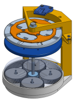
My long-term goal is to create my own motors for a dual motor aircraft/drone. The design of the aircraft is to follow the idea of tilt-rotors, to avoid my personal fear of landing aircraft and to solve the fact that i don't have any good makeshift runways around me. I plan on having several models as I work up to a full-scale model using a home-built turbine for power generation (this is a long shot and it is going to be a lot of fun). The goal there is to have a circuit to build both the ESC and the generator using the same controller board. The current iteration is just to get airborne with two motors and a battery, with a weight less than 5 lbs. This is the long term project and hopefully will explain some of my design choices like no back iron to drop weight.

Everything I'm making is out of 3D printed parts for prototyping. Eventually I'll move into epoxy as that seems to have a great deal of help making a sturdy stator. The tolerances aren't great, one side of my bed constantly detaches at a certain line which is annoying. I haven't tried any glues though and I'm still using the base glass plate from Creality.

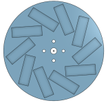
My motor design is based on a 10p/9s yokeless double-rotor axial motor. The frame is held together by three 1/4" bolts with a 1/4" bolts as the shaft. I'm using 26 gauge magnet wire from McMaster, which makes winding coils a pain cause it has to have so many windings. So far, I've used a typical coil for each stator mount with about 200~ coils on each. I made a 1P serpentine winding to use and that made the motor run quite happy as well. I liked that winding much more since I could just create a giant loop and then slot it into place, but I saw Halback Hero's post where he used litz wire to create a layered serpentine coil and I'm very interested into working towards that, with the addition of metal slots for some extra torque if the weight is justified. I'm using M3 screws to bolt the typical stator coils to the frame for structural support and for a bit of iron in the electromagnet. My magnets are 30x10 mm which seem to be a lot more rectangular than most of the magnets I've seen used on here. My model includes an ability to rotate the magnets to 45 degrees. a previous model had a great success with that and i wanted to try angled vs un-angled on this motor as well. The air gaps are a bit extreme, most staying around 1mm airgap between the stator edges and then another 2mm due to the pla stator plate that it's built onto.

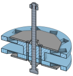
The Rotor (100 mm diameter)
1721832079535.png
1721832180160.png
there are screws on either side of the rotor holding the grey motor coverplates to the stator, as well as ensuring the rotors don't slip. There's plenty of magnetic attraction between them to hold it steady without it.
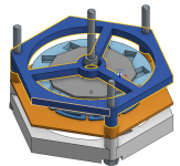
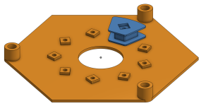
The Stator (with 1 coil)
1721832233500.png
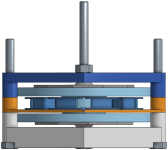
The Whole Motor
1721832386555.png
1721832429705.png
1721832839893.png


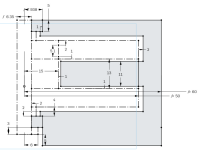
These are all from OnShape, which is a free cloud CAD software I found which is really helpful since i switch computers throughout the day.

I have a custom ESC that runs on hall effect sensors, it's currently on a breadboard as i got too eager on my perf board and packed it too tightly. I'm aiming to create a microcontroller board for each motor on the tilt rotor so they can be plug and play rotors instead of having to adjust setting in the flight controller. My power supply comes from a 0V-48V 10amp power box which is set to 12V to mimic the nimh pack I have.. A previous 3P motor had gotten to about 2-3k rpm at 12V per my Arduino code. I've been meaning to put together a test stand to measure torque using an arm and a load cell.

I'm currently printing this version, but I forgot to add the mounting for the hall effect board under the shaft on the bottom bracket, which is the piece I started printing this morning before I left for work. I'll get that redesigned and work on coding in that AS5600 into the testbed micro-controller.
 
Hello and welcome!

That sounds like an interesting project, I sure hope you'll succeed.

I don't know if you've already seen this thread, but it is probably the best one we got here about DIY axial flux motors:

As you can see in this thread, APL got pretty far in developping his motor and even though it was very well built and carefully designed it still didn't work too well.

3D printing will be too weak for any application where you'd need to have decent power, it will be ok for developping very low power prototypes, but don't expect too much from it as the rigidity won't be there to give you a reliable gap. For example, I doubt the orange part is going to make it as it is very thin and it will warp severely as soon as you will give any power to the coils, because they will start interacting with the magnets which will either pull them towards the magnets or push them away depending on the current direction.

But anyway, I'll be happy to follow the progress, good luck in your project!
 
Last edited:
Thanks Dui ni Shuo de dui! APL was doing some great work on that project and it was really astounding. I'm hoping to get into the 300 watt range for this motor and see how that fairs.

I'm still printing everything out for this motor, had a few design slips and had to get things reshaped.

I've been hunting for an explanation between 120 degree and 150 trapezoidal control for ESCs. does any one have a good explanation or a document for this?

Thanks,

Erik
 
Hello everyone!

I got all the parts printed two weeks ago and assembled. Unsurprisingly, there were some tolerance issues on the rotor-stator air gap like Dui ni Shuo de dui pointed out there would be. The top half of the rotor seemed to be the problem and removing it allowed for smooth rotation, aside from cogging. It looks like the top of the bottom rotor is sitting flat with the top of my coils, so I'll have to adjust for that in CAD. For now, one rotor should work to get work at a lower efficiency. I had to reprint the bottom as I had guesstimated the layout for the AS5600 I was using and because the positioning magnet needs a spacer from the 1/4" bolt I'm using as a shaft. Placing the 4x1mm magnet on the shaft directly just short circuited the magnet, so it has a small spacer and the AS5600 screwed beneath.

This is the current set-up.
IMG_5036.JPEG


On the left is the 0-48V 10A power supply. It was some cheap Chinese power supply and it's been doing the job for nearly two years now. It handles my accidental short-circuits plenty well, even if my breadboards don't. For my testing, it can be anywhere from 10-17 volts to work with my gate drivers.

The small circuit board beneath that, with the red and blue leds, is my mock motor. It uses the LED's diode to rectify the signal into a fake north/south. it's been helpful in ensuring that the rotation follows in the correct direction and testing any short circuits without hurting a motor.

The Breadboard in the back, next to the Arduino, is connected to a 5V 2A USB plug. There's a button on their that lets me connect the 5V to the ATMEGA328 on the lower breadboard which lets me use test power. It's helpful for checking that my code works without having to turn on the power supply.

The middle breadboard is my ESC/BEC. It has (6) MOSFETS, (3) gate drivers, (1) 5V Regulator, (1) voltage divider, (1) current reader not implemented and the throttle controller.

The bottom breadboard has the ATMEGA328 that I've programmed to use it's hardware PWM and analog signals. I'm still working on the code, but as you can see, it's not connected to the computer or Arduino at all. I'm still working on coding some safety measures to limit shoot-through and also including I2C instructions for future implementation as isolated motor systems. The code only works with counter-clockwise motion as that's how my three phases work at the moment. Going clockwise cause's a minimum of one short circuit on any phase. There should be an easy switch by implementing the AS5600's direction pin.
The next step in the programming side is to create a testbed platform uC which can read information from the motor uC and display it on a LCD screen and control the power supply.

The motor is held together by (3) 1/4" bolts which mounts the frame together. I haven't re-calibrated my 3D printer in a while, but there's only a slight elephant foot which is good. The AS5600's wires are out from under it, the I2C and power wires. The little arm on top was a test print for a torque arm to connect this to a load cell, the goal being to tighten the fit using a screw and get different torques for different rpm and test out the kV etc.
IMG_5038.JPEG
I plugged in the motor after checking all my wiring and it runs like a penguin in the desert, which is to say that it kicks for about 10 seconds before stalling. It has a lot of kick, but it's fighting itself.
I was falling asleep last night trying to figure out why it was mis-behaving and realized that the position magnet isn't aligned to the stator coils at all! it's in a completely random direction! My goal for the next step is to include a start-up procedure by turning on phase 1 and splitting the ground on phase 2 & 3 so that i can find the offset between the position magnet and the motor. That should allow me to code in the offset to the AS56000 so that the phase changes are aligned.
 
Wow, amazing. I like how you said you were building a motor and then you just casually built a controller on a breadboard like it's some trivial stuff.

Could you elaborate/dumb it down so we could try and understand how you made it? I'd really like to try and build a small motor controller at some point but I'm never really sure about how I should choose the components and how to protect stuff so it doesn't blow up. Really don't know where to start actually.

Great job mate, keep us posted!
 
Absolutely! I probably spent my first year of this project just working on understanding the components of the circuit and messing around with them, and a heavy bit of magic smoke escaping from the various components. I'll try to get something written up this week!
 
So! Writing about the compiled knowledge of motor controller hardware/software. I will forewarn that I probably have some gross misconceptions about how some pieces work but I'll do my best to explain them! I'll list off the pieces I'm using for my circuit at the top here.

Mosfet: IRFB7545
Gate Driver: IR2110

So a motor driver is basically just 3 half-bridges. That's a simplification that helped me a lot and it breaks down the entire system into one simpler piece. MOSFETs are chosen and used because they have very low resistance when properly powered and are mostly isolated between the gate and the current flowing through. They're also voltage based, instead of the BJT's current based switches. As long as you supply a certain voltage, the MOSFETs will stay on but with BJT's, they have a higher resistance when on and require a decent current through them to pass current.

Some basic MOSFET terminology to establish, because they follow electron flow instead of the franklin method.

1723215977764.png

  • Gate (G): this is the trigger for the MOSFET. this is where voltage is supplied to to turn a mosfet on or off.
  • Drain (D): This is the higher side in typical convention.
  • Source (S): This is the lower side in typical convention.
There are two types or MOSFETS, n-types and p-types. These work similar to their BJT counterparts if you're familiar. one major difference is the interaction of the gate. in BJTs, you supply current that opens the current flow through the BJT. in MOSFETs, you charge the gate (it acts like a tin capacitor) and once you charge/discharge it to the correct voltage, the gate opens.

P-types have a NO (normally open) architecture, and you have to supply a voltage to the gate that is X volts below the supply voltage (Drain) to shut it off. This makes them easier to use on high-side applications as you can control a voltage divider to create a lower voltage at the gate. You wouldn't need to have a gate driver to control it.

N-types have a NO (normally closed) architecture. You have to supply a voltage to the gate that is X voltage above the ground reference (Source) to turn it on. This makes them easy to use on low-side applications (load is above them in series) as the ground reference is actually ground, so logic voltages can turn them on.

I chose to use N-types as they have lower resistance (between 10x and 100x less) than P-types. this creates a need for the gate driver and circuitry, but then again, where's the fun if it's easy? While they have low resistances when they're fully charged, the capacitive gates still have to charge which creates a time gradient where the resistance is decreasing. the gate drivers assist by being designed to dump a large current onto the gate line to rapidly charge or discharge the gate.

So then half-bridges! I'm sure you're familiar with them, they're in everything from radios to, well, motor drivers. There are simple ones like the L293D which comes with the Arduino kits, and more complicated ones like the ones in high-speed motor drivers. It consists of two switches, one high-side and one low side, and some form of driver for the gates. See the image below from the IR2110 gate driver cutsheet , its a great model of a half-bridge circuit and the IR2110 doesn't do a ton of magic inside of it so it's more configurable and therefore more fun to me.

1723212589834.png

The left side of the IR2110 there is just handling uC signals and a logic shutdown gate. All of these operate on logic voltage of 5V. For our purpose of learning, we can assume that a pulse on the uC line opens up the respective MOSFET, HIN to HO and LIN to LO (high side input to high side output, low side input to low side output). We'll come back to the signal side more once we get through what all is happening on the MOSFET side.

I'm going to focus on the low-side MOSFET first as it's the simple case. It really only uses the three bottom right pins, Vcc Com and Lo.
  • Vcc is NOT always the battery voltage. the IR2110 can handle up to 25V on Vcc but recommends a maximum of 20V and a minimum of 10 V.
  • Com is the ground side of the MOSFETs. This ensures that the 5V logic side and the power side can be isolated from each other (mine doesn't though).​
  • The capacitor between these helps supply energy when it's suddenly pulsed out of the gate driver.​
  • Lo provides another internal half bridge (half-bridge inception) to control setting the gate voltage high or low.​
There is a resistor in series between the gate driver and the MOSFET. This seems like a waste but this can be one of the more important components. Part of what makes these gate drivers so helpful is that they can supply large amounts of current to quickly charge the gate node. However, and this is something that i have left up to some random person on the internet, the node connecting the LO pin to the gate capacitance acts like an LC circuit and can create ringing. this means that the MOSFET isn't fully active, but bouncing between open and closed until the tiny resistance of the wire dissipates that fluctuation. The resistor damps that oscillation so that it can go from ringing to an overdamped curve. There's a way to calculate this if you have the capacitance of the MOSFET and the gate driver current, but I've just left it at 10 or 20 ohms. I don't have an oscilloscope to evaluate this though.
You also don't have to have some beefy resistor for this either. it deals with 2 amps of current for very brief moments, so the wattage never reaches the 1/4 W rating of typical resistors.

Now for the high-side MOSFET and the fun circuitry that happens there. and a bonus circuit called a charge pump that has some merit for other purposes but not really for our motor drivers. So we have the pins HO, Vs and Vb.
  • Vss is the battery supply voltage. this is dictated by whatever your MOSFETs can handle. Mine can handle 60V and the gate driver can handle up to 600 V.​
  • Vs is connected to the half-bridge output. this makes sense as this is the ground-base for the MOSFET to let the current flow through.​
  • Vb is the boosted voltage pin for the high-side MOSFET.​
  • The capacitor diode connection is part of a charge pump circuit to create a V_batt+Vcc voltage level.​
So this part of the circuit is what is wild to me still. i want to be clear, you cannot use a low-side pin to operate the high-side MOSEFT. You will destroy components. The circuit idea is the same as the low-side MOSFET, but you have to boost the gate voltage above the battery voltage.
Think of it this way, consider the voltages once the MOSFET is open, the drain and source are both V_batt. an N-type MOSFET requires the gate to be X volts above the source pin. so we need a voltage of V_batt + X to keep the MOSFET open! but we only have V_batt available! This is where that capacitor and diode come in.
While the half-bridge is low, Vcc flows through the diode and charges the capacitor, who's positive side is now Vcc minus the diode drop and who's negative side is connected to ground through the low-side MOSFET. When the high side MOSFET is turned on, momentarily, the source is at ground and the gate voltage is just at Vcc minus diode drop. As the current flows through the mosfet, the MOSFET source is shifting up to V_batt BUT the capacitor's ground pin is also increasing! the diode prevents back-flow and Vb is boosted up to V_batt+Vcc-diode drop! This means, relative to the mosfet source, the gate is still at V_cc-diode drop. Sadly, circuits aren't ideal and the capacitor will discharge and Vb will drop causing the MOSFET to shut off. the key to this is cycling faster than the capacitor discharges. i forget what capacitance mine have but they can stay open for about 1/10 of a second, but my motor still cycles faster than that.
The resistor performs the same function as it does for the low-side MOSFET.

That provides a pretty compressive guide as to what happens for each half-bridge in a motor controller, not including how a microcontroller determines when to switch the mosfets. I've written plenty of code to try to accomplish that, but i'm always messing with that. I realized that, for as much as i have fought sensorless design, i might have to use it to detect a specific angle for my hall effect sensor to center itself on.

Feel free to ask questions and i'll try to find any of the specific documents i learned things from.
 
Motor Update!

It's running pretty smoothly now. It's still very slow for 12V in my mind, but i haven't finished the display uC to see any of the actual data coming out of it. It has some good kick to it, it feels like its getting a good use of power coming out, but i think it only has about an amp flowing through it as the motor itself has a phase resistance of 8-9 ohms. It's just one strand wrapped around a PLA core with a M3 screw in it. If I tighten it up, the cogging in a minor problem.

I solved the hall effect resolution problem (finding the actual phase A angle) by setting A phase to be high and split the current between phases B & C. That start-up gets it spinning but i think i still need to trim that number.

It has two different running modes, depending on if it's counter clock wise or clockwise. This is just due to my code opening and closing gates in strange ways. I still need to solder some connections so i can plug it into a typical ESC and let that run instead.
 
Installed the serpentine winding instead of the coils. only a one-phase version though. it's running smoother and I think that's due to the evenness of the windings. I winding all the single coils a bit wildly with 26 guage wire, so the magnetic field is very uneven. Serpentine winding helps that.

Having the threaded rod as a shaft meant I can manipulate the tolerance for the rotor which allows for some easy adjusting.

Also, i've never figured this out but does anyone else get really dizzy around high frequency electronics? I must be doing something wrong because running my circuit makes feel nauseous.
 
Also, i've never figured this out but does anyone else get really dizzy around high frequency electronics? I must be doing something wrong because running my circuit makes feel nauseous.
I haven't felt nauseous, but certain power supplies in computer monitors and some electronics are loud enough at their switching frequency to give me a mild headache.
What switching frequency are you using? (power stage, dc-dc)
 
I'm not sure what frequency my power supply is running at, i know it takes wall voltage at 60 hz but i'm sure that's not the source as it's probably (hopefully) properly engineered.

My ESC is running on a 1 Mhz atmega chip @ 1/8 speed for the 8-bit timers. PWM would be 488.2 Hz then, which i can hear while I turn the change the throttle. I'm working on figuring out how to boost that to >20 kHz so that I don't have to hear that, i don't need my motor being a speaker too.

There is probably some ringing in the mosfets, gate drivers, etc. That's going to be something i need help identitfying.
 
Last edited:
I had the motor working for a while but it's gone kaput now. I'm confident that i have the correct BLDC pattern for a 3-phase motor ( Ab, Ac, Bc, Ba, Ca, Cb ) but my motor seems to get stuck on a step. It bounces back and forth between two of the phases.
If I disconnect the wires, I can check that the ESC section is getting the correct signals. It doesn't miss any phases.
Connecting the power wires, It goes through it's start-up procedure to find the location of A phase and then shifts the hall effect sensors accordingly. Then it just jogs in place which is disappointing.

My only concern is that I've messed up the logic for the as5600 hall effect sensor and now it's just getting confused.

Other Motor Updates:

1) I've added another ATMEGA328 to the project in the form of a master controller. I've split the code between motor controller and master controller (for displays, computer interaction, etc). This doubles the pin count which I desperately needed. This master controller also has safety features (a requirement, per the wife) which includes a relay to disable power to the ESC and ensure that all I2C components are connected.
I'm also using it to set all the various parameters (poles, stators, phases, commutation modes) instead of having to define them in the code. This should help me tinker with designs without having to re-program the system every time.

2) I re-breadboarded my project as the tangle of wires was a mess. It's now on (2) 60-ish row breadboards with the master controller on a separate (2) 30-ish row breadboards.

3) I've put aside the serpentine windings for the time to focus on getting more torque out of the motor by using the coils with the set screws as small (probably saturated) cores. I still haven't found a way to get a back iron for my project sadly.

4) I played with the idea of increasing the rotor diameter to increase the poles from 8 to about 20, but i didn't find any winding combinations that I liked. in the end, I'm switching from a 8p9n to a 8p6n for balance. I noticed that i am losing winding factor but gaining a balanced stator which i preferred.

5) I had gone through the forum looking for any info on angled magnets as shown in my first post. I didn't find anything conculsive and i'm wondering if that's making this ineffiecent. I'll have to print another version to see if i can measure any difference.

6) I'm switching from 26 gauge wire to 20 gauge wire. I believe that the resistance on the small wire was preventing me from getting all the amps that I could get. I found that Reminginton had it for a great price, better than the McMaster core price I had initially used. This also marks that I've now used nearly a full pound of copper messing around with this project.
 
IMG_5136.JPEG
I have been meaning to take more pictures at different stages but all i have is this one of the serpentine winding installed. just one phase but it ran plenty smooth. The gap between the rotor and the stator is only 1mm but it doesn't scratch while running.
 
I was trying to post about a question I had and instead I made this post about the previous iterations of my designs. So I'll just make two posts.

Mk III Motor

IMG_3906.JPEG IMG_3998.JPEG
1724417968984.png
In my previous smaller motors, I used hall effect sensors to directly measure the rotor magnets and used those to compute an electrical angle (aka 360 degrees is equal to one full sine wave above a coil). I could do this with two linear hall effects or three latch hall effects. This was surprisingly easy to implement and just used two analog inputs into the uC. Using some magic math of tangents and some smoothing, I got this model running really well, but i didn't like that all the mounting for the rotor was beneath the rotor, so i started designing the Mk IV pretty soon afterwards. The Mk III was also a headache to print as the base took a very long time and had a lot of unused space.

MK IV
1724417923217.png1724418732998.png

Mk IV started out as a horizontal motor, hence that strange backing. I thought that would solve some stability problems but i ended up moving away from that and kept the vertical design. I solved the rotor wobble problem by having that bearing at the bottom act as a tolerance which was very helpful. This was a 8p6n motor that was running blindly, aka there was a timer switching phases and not the hall effects, as those were still super glued to the previous motor. I've never gone back and remade one of the linear hall effect readers, but i have a little jig for holding them to solder. it was much better to print, but the assembly of it really bugged me.
Part of the goal of this design was also to have a gear train at the bottom, as i was obsessed with planetary gears at the time. I never got around to that because I switched to Mk V pretty quickly after that and that's when i started posting on here!

Mark VI features a better stacked design, so i can assembly the motor vertically and everything screws down piece by piece. I have the same 1/4" bolts and nuts tightening everything into place. The major improvement of mark VI was using a derived sketch in Onshape so that everything can be built off of the same sketch, so modifying the rotor thickness also changes the height of the base as well. I've added some nuts inside of the rotor to ensure there is no slip, as the current version has started to slip off the threads. The nuts are sandwiched between the magnet carrier portion of the rotor and the magnet cover.
Speaking of Onshape, since I have a free account, you can go in and see any of the projects that i've designed/designing/tinkering with. Mostly this motor, with a notable inclusion of a actuated propeller meant for a constant speed propeller project and a telescope i've been meaning to build for years now.
 
Okay so now I can actually do the help request I originally meant to ask for.

Why does my current hall effect sensor have problems that wern't present before?
In those previous versions, i used a home made linear hall effect sensor to measure the rotation angle of the rotor. Since I had been using them on one pole of pairs, one electrical revolution created a full range on the hall effect sensors. It worked wonderfully. I think this is because it was measuring the electrical revolutions directly.

In my current version using the AS5600 hall effect, one mechanical revolution is the full range of the hall effect and i have to divide the 4096 steps the hall effect makes into 10 electrical revolutions for the 10 different poles. I've been using a remainder function to reduce the scale to 409 steps per phase. What confuses me is that the motor seems to jog back and forth, and turning it by hand feels like it gets stuck in a magnetic valley, as if i push it clock-wise, the next phase pushes it counter-clockwise and if i push it counter clock wise, it pushes clock wise.

Wait. I think I've answered my own question explaining it. There shouldn't be 10 electrical revolutions, there should be 5 electrical revolutions. Each electrical revolution is made of a north and south pole, so the electrical revolution should be half the number of magnets used. I'll test this when i get home.

Finding the Offset without using a voltage-dividing zero-crossing point?
My other concern was if my offset-finding method was flawed. Like I had mentioned before, my idea was to set the motor to have 1 phase amp on A, -0.5 amps on B and -0.5 amps on C. My thought was that this would align the rotor to the stator and then measure the random offset of the diametric 1mm magnet under the rotor. This would set the AS5600 to start the measurements from that angle and measure degrees from there.

I think my mistake here is in the logic of the offset command. I'll use the example to prove my point.
Say the rotor gets aligned as above. The AS5600 measures 17 degrees. This location should be the zero point for all measurements. I've mistakenly been measuring this and adding it to the offset. So now, the neutral point is 34 degrees instead of 0 degrees. I'll need to adjust this but it's just a simple negative sign on the code.

Other Motor Updates
I forgot to add this picture earlier but its the basis of the LCD master controller. It'll have three buttons for menus and changing values, and also have the throttle control to transmit to the motor controller of I2C. And no, it's not measuring 6.7 amps, the current op amp was never fixed when i was changing resistors so the voltage/amp relationship is wildly off.

IMG_4897.JPEG
 
IT WORKS! It's surprising how easy some changes can be.

I was wrong about the offset needing to be negative. That made the Motor VERY unhappy. fair enough.

The magnetic poles was an easy fix of dividing by two in the right place! That got it running and I think all that is left is the tuning of the offset parameter to make sure the shaft and the stator don't slip!
It has a tiny tolerance somewhere that makes a scratching noise during a tiny portion of the rotation but it seems to be a shaft problem, not between the stators and coils. I'll set up my youtube channel this weekend and upload a video of it running. I've ran it twice since I got home with two different speeds ( I believe due to the offset being better aligned the second time and creating a MUCH higher speed.) While typing this out, I slapped on the propeller i printed and it went insanely fast. I'll need to get my master controller finished so i can get measurements!

As you can guess, I'm quite happy. The light pen was trying to find the scratching noise.

IMG_5165.JPEGIMG_5164.JPEG
 
So! Writing about the compiled knowledge of motor controller hardware/software. I will forewarn that I probably have some gross misconceptions about how some pieces work but I'll do my best to explain them! I'll list off the pieces I'm using for my circuit at the top here.

Mosfet: IRFB7545
Gate Driver: IR2110

So a motor driver is basically just 3 half-bridges. That's a simplification that helped me a lot and it breaks down the entire system into one simpler piece. MOSFETs are chosen and used because they have very low resistance when properly powered and are mostly isolated between the gate and the current flowing through. They're also voltage based, instead of the BJT's current based switches. As long as you supply a certain voltage, the MOSFETs will stay on but with BJT's, they have a higher resistance when on and require a decent current through them to pass current.

Some basic MOSFET terminology to establish, because they follow electron flow instead of the franklin method.

View attachment 357902

  • Gate (G): this is the trigger for the MOSFET. this is where voltage is supplied to to turn a mosfet on or off.
  • Drain (D): This is the higher side in typical convention.
  • Source (S): This is the lower side in typical convention.
There are two types or MOSFETS, n-types and p-types. These work similar to their BJT counterparts if you're familiar. one major difference is the interaction of the gate. in BJTs, you supply current that opens the current flow through the BJT. in MOSFETs, you charge the gate (it acts like a tin capacitor) and once you charge/discharge it to the correct voltage, the gate opens.

P-types have a NO (normally open) architecture, and you have to supply a voltage to the gate that is X volts below the supply voltage (Drain) to shut it off. This makes them easier to use on high-side applications as you can control a voltage divider to create a lower voltage at the gate. You wouldn't need to have a gate driver to control it.

N-types have a NO (normally closed) architecture. You have to supply a voltage to the gate that is X voltage above the ground reference (Source) to turn it on. This makes them easy to use on low-side applications (load is above them in series) as the ground reference is actually ground, so logic voltages can turn them on.

I chose to use N-types as they have lower resistance (between 10x and 100x less) than P-types. this creates a need for the gate driver and circuitry, but then again, where's the fun if it's easy? While they have low resistances when they're fully charged, the capacitive gates still have to charge which creates a time gradient where the resistance is decreasing. the gate drivers assist by being designed to dump a large current onto the gate line to rapidly charge or discharge the gate.

So then half-bridges! I'm sure you're familiar with them, they're in everything from radios to, well, motor drivers. There are simple ones like the L293D which comes with the Arduino kits, and more complicated ones like the ones in high-speed motor drivers. It consists of two switches, one high-side and one low side, and some form of driver for the gates. See the image below from the IR2110 gate driver cutsheet , its a great model of a half-bridge circuit and the IR2110 doesn't do a ton of magic inside of it so it's more configurable and therefore more fun to me.

View attachment 357901

The left side of the IR2110 there is just handling uC signals and a logic shutdown gate. All of these operate on logic voltage of 5V. For our purpose of learning, we can assume that a pulse on the uC line opens up the respective MOSFET, HIN to HO and LIN to LO (high side input to high side output, low side input to low side output). We'll come back to the signal side more once we get through what all is happening on the MOSFET side.

I'm going to focus on the low-side MOSFET first as it's the simple case. It really only uses the three bottom right pins, Vcc Com and Lo.
  • Vcc is NOT always the battery voltage. the IR2110 can handle up to 25V on Vcc but recommends a maximum of 20V and a minimum of 10 V.
  • Com is the ground side of the MOSFETs. This ensures that the 5V logic side and the power side can be isolated from each other (mine doesn't though).​
  • The capacitor between these helps supply energy when it's suddenly pulsed out of the gate driver.​
  • Lo provides another internal half bridge (half-bridge inception) to control setting the gate voltage high or low.​
There is a resistor in series between the gate driver and the MOSFET. This seems like a waste but this can be one of the more important components. Part of what makes these gate drivers so helpful is that they can supply large amounts of current to quickly charge the gate node. However, and this is something that i have left up to some random person on the internet, the node connecting the LO pin to the gate capacitance acts like an LC circuit and can create ringing. this means that the MOSFET isn't fully active, but bouncing between open and closed until the tiny resistance of the wire dissipates that fluctuation. The resistor damps that oscillation so that it can go from ringing to an overdamped curve. There's a way to calculate this if you have the capacitance of the MOSFET and the gate driver current, but I've just left it at 10 or 20 ohms. I don't have an oscilloscope to evaluate this though.
You also don't have to have some beefy resistor for this either. it deals with 2 amps of current for very brief moments, so the wattage never reaches the 1/4 W rating of typical resistors.

Now for the high-side MOSFET and the fun circuitry that happens there. and a bonus circuit called a charge pump that has some merit for other purposes but not really for our motor drivers. So we have the pins HO, Vs and Vb.
  • Vss is the battery supply voltage. this is dictated by whatever your MOSFETs can handle. Mine can handle 60V and the gate driver can handle up to 600 V.​
  • Vs is connected to the half-bridge output. this makes sense as this is the ground-base for the MOSFET to let the current flow through.​
  • Vb is the boosted voltage pin for the high-side MOSFET.​
  • The capacitor diode connection is part of a charge pump circuit to create a V_batt+Vcc voltage level.​
So this part of the circuit is what is wild to me still. i want to be clear, you cannot use a low-side pin to operate the high-side MOSEFT. You will destroy components. The circuit idea is the same as the low-side MOSFET, but you have to boost the gate voltage above the battery voltage.
Think of it this way, consider the voltages once the MOSFET is open, the drain and source are both V_batt. an N-type MOSFET requires the gate to be X volts above the source pin. so we need a voltage of V_batt + X to keep the MOSFET open! but we only have V_batt available! This is where that capacitor and diode come in.
While the half-bridge is low, Vcc flows through the diode and charges the capacitor, who's positive side is now Vcc minus the diode drop and who's negative side is connected to ground through the low-side MOSFET. When the high side MOSFET is turned on, momentarily, the source is at ground and the gate voltage is just at Vcc minus diode drop. As the current flows through the mosfet, the MOSFET source is shifting up to V_batt BUT the capacitor's ground pin is also increasing! the diode prevents back-flow and Vb is boosted up to V_batt+Vcc-diode drop! This means, relative to the mosfet source, the gate is still at V_cc-diode drop. Sadly, circuits aren't ideal and the capacitor will discharge and Vb will drop causing the MOSFET to shut off. the key to this is cycling faster than the capacitor discharges. i forget what capacitance mine have but they can stay open for about 1/10 of a second, but my motor still cycles faster than that.
The resistor performs the same function as it does for the low-side MOSFET.

That provides a pretty compressive guide as to what happens for each half-bridge in a motor controller, not including how a microcontroller determines when to switch the mosfets. I've written plenty of code to try to accomplish that, but i'm always messing with that. I realized that, for as much as i have fought sensorless design, i might have to use it to detect a specific angle for my hall effect sensor to center itself on.

Feel free to ask questions and i'll try to find any of the specific documents i learned things from.
Thank you for this great write up.
The high side mosfet part was particularily interesting, I didn't know about this whole charge pump thing but it makes a ton of sense now!
Thanks again!
 
Back
Top