Byte
1 kW
Just beautiful!
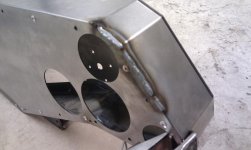
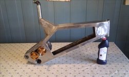
Whiplash said:For sheet metal, a stitch weld is better suited. Set your gas flow higher than normal, use a bigger nozzle on the gun, and just use a series of quick tacks in a grow all the way down and it helps to pre heat the part a bit with a propane torch to spread the heat over the surface before welding to help minimize warping.

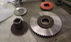
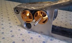
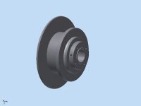
Ratking said:Since I don't have the skills to draw a sprocket properly and I cant find the sprocket generator in Inventor, the sprockets will show as a blank disk.


E-racer said:Yea im self taught in Inventor I've been using autodesk stuff since 10th grade. I took engr graphics 1 and 2 in my undergrad but that was using solidworks and it was incredibly basic/waste of my time. I have some experience with CFD from our formula SAE restrictor design. I'm learning how to use the FEA features slowly.
Craigh85 said:Hi Ratking your builds looking great. Quick question on your nickel sheet for tabbing the cells together, I recently got a load of copper sheet approx 0.5mm thick to join my cells, is nickel a better material to use? My spot welder is based around a microwave oven transformer.

Craigh85 said:dohh, ahh well could mabe just solder the copper then. nickel doesnt seem that easy to come by here unfortunately need to investigate further. Thanks for the advice , all the best . Craig