Electric downhill/freeride bike

Hello

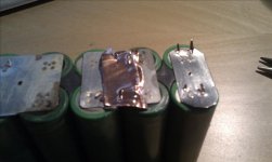
Been doing some boring stuff lately. That involves sorting hundred of used makita cells.
My conclusion is, as well as Doctorbass also says, the cells have to keep their voltage more than a day, less than 40mOhm of resistance, and have good capacity. Also, every cell where I can spot electrolyte being let out, the cell is rejected.

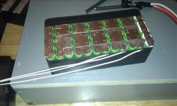
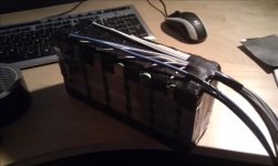
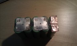
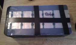
As you can guess, this takes time. But I've finally made my battery packs thats going in to the bike. I still need to weld the power and balancing wires to the packs, but as for now I am satisfied with the result. I did not get as many cells into the bike as I wanted, but the pack is made out of 192 cells arranged into 12s16p(44.4v 24Ah). I used my chepo spotwelder, that to my surprise did a very good job.
 

Attachments

  • IMAG0060_518x310.jpg
    IMAG0060_518x310.jpg
    54.5 KB · Views: 2,456
  • IMAG0067_518x310.jpg
    IMAG0067_518x310.jpg
    49.3 KB · Views: 2,456
I'm sure you could beta the RC cycle analyst. I agree that throttling this thing properly is going to be a challenge.
 
What does a pack like that weigh? It looks heat, why not LiPo?
 
Whiplash said:
What does a pack like that weigh? It looks heat, why not LiPo?

Compared to the hard case lipos I've would been using there are only a few grams difference. My pack is 8.4 kg and the lipos would only be a few hundred grams less for the same capacity.
Some of the reasons are that I designed the frame around these cells, and there are no lipo packs that fi good enough for me using them. If the bike is perfect and I see a need for another one, I will make one a bit wider so that it will fit two hardcase packs in the width of the frame making it possible to have 1.5 kwh++. That all the batteries was free for me also helped :)

PS. What do you mean by "It looks heat?"
 
Sorry, autocorrect on my phone... I meant they look heavy but they aren't! Nice build especially considering the cells were free!
 
Batteries are almost complete, I will show how I did it for anyone that wants some inspiration how it could be done.
I first tried to solder all the balancing leads to the tabs, but the wire plus solder was to thick for my frame if I wanted a sheet of protecting plastic so I had to make an alternative. Then I came up with his route.
I think its much cleaner and should be atleast as good. I'm starting to love spot welding. Its so easy and clean.

I tried to discharge the pack, and I got between 9-10Ah at 1.2C out of a 12s6p pack of konions. That was from 4.125v-3.17v. I did not want to go to low, even though the data sheet says 4.2-2.5v.
 

Attachments

  • IMAG0080.jpg
    IMAG0080.jpg
    34.8 KB · Views: 2,616
  • IMAG0081.jpg
    IMAG0081.jpg
    28.7 KB · Views: 2,616
  • IMAG0082.jpg
    IMAG0082.jpg
    49.1 KB · Views: 2,616
  • IMAG0086.jpg
    IMAG0086.jpg
    34 KB · Views: 2,616
  • IMAG0087.jpg
    IMAG0087.jpg
    37 KB · Views: 2,616
Just spamming my own post, need to update my build with the newest from Ratking's workshop.
Since I have limited space, and wanted both a freewheel and torque limiter I had to think new and hope this solution is the best compromise.
Short explanation:
First part is the sprocket adapter for the 25# sprocket, and on the same adapter a 30mm one way bearing is pressed on. A outer adapter is pressed at the outer part of the one way bearing and the torque limiter is fitted with a 420 sprocket.
I still need to make the last part that compress the two disks and the sprocket, but that is a small part to make.
The whole part is less than 40mm thick, I can see any way to make this any slimmer. I hope it does a descent job.
 

Attachments

  • IMAG0088.jpg
    IMAG0088.jpg
    31.7 KB · Views: 2,612
  • IMAG0089.jpg
    IMAG0089.jpg
    30.7 KB · Views: 2,612
  • IMAG0090.jpg
    IMAG0090.jpg
    29.4 KB · Views: 2,612
  • IMAG0091.jpg
    IMAG0091.jpg
    27.3 KB · Views: 2,612
  • IMAG0092.jpg
    IMAG0092.jpg
    36.1 KB · Views: 2,612
  • IMAG0094.jpg
    IMAG0094.jpg
    51.2 KB · Views: 2,612
Hello!

I have been following your build, it's very impressive. I am also working with the 18650v cells you are using. I am planning on CD welding tabs as well, basically we are following similar battery paths.
I liked your balance leads at first, but I foresee a potential issue. Where you have bent those tabs over the edge at the 90 degree angle, they are pressing directly against the thin plastic layer. With vibration I am worried the sharp edges of the tab might slowly but surely cut through the plastic; i have seen this on several Makita packs, where the sharp edge of a tab eventually cut through the green plastic and shorted the pack to the negative body housing, and thsoe tabs were on top, horizontal to the plastic layer and they still cut through. I would think one thin insulating layer like electrical tape would at least double the shorting protection, but I would be generally weary about bending those tabs like that at all; the edge might end up slightly rounded, causing the sharp edges of the tabs to actually slightly point inwards towards the plastic...


Anyway, maybe I'm just being paranoid, but I'd hate to see you lose free batts :). What do you think?
 
Andje said:
Hello!

I have been following your build, it's very impressive. I am also working with the 18650v cells you are using. I am planning on CD welding tabs as well, basically we are following similar battery paths.
I liked your balance leads at first, but I foresee a potential issue. Where you have bent those tabs over the edge at the 90 degree angle, they are pressing directly against the thin plastic layer. With vibration I am worried the sharp edges of the tab might slowly but surely cut through the plastic; i have seen this on several Makita packs, where the sharp edge of a tab eventually cut through the green plastic and shorted the pack to the negative body housing, and thsoe tabs were on top, horizontal to the plastic layer and they still cut through. I would think one thin insulating layer like electrical tape would at least double the shorting protection, but I would be generally weary about bending those tabs like that at all; the edge might end up slightly rounded, causing the sharp edges of the tabs to actually slightly point inwards towards the plastic...


Anyway, maybe I'm just being paranoid, but I'd hate to see you lose free batts :). What do you think?

Nice observation, but I have welded all the balance leads to the negative side of the battery, so if any of the leads get trough the black tape and the green plastic it doesn't do anything, because it the same potential. And I also welded the nickel sheet on top of the already existing tabs, I don't see that it could make any short easily.
This is a experiment from my side. It only costs my time, and that is ok for now.
If it fails, I will be one step closer to a better pack.
 
Just tried to spot weld some thin copper sheet(.2mm) and it worked prey good. I don't know what characterise a good weld, but when the copper
rather want to be on the battery tab than keeping the sheet in one piece I would say it it good.
I would love to get some input on this, because I have always heard that copper is hard to spot weld whit this kind of welder.
 

Attachments

  • IMAG0095.jpg
    IMAG0095.jpg
    33.5 KB · Views: 2,594
  • IMAG0097.jpg
    IMAG0097.jpg
    36.8 KB · Views: 2,594
Just go myself a little package containing a few 52t 130 bcd rear sprockets.
Did you know that two ordinary bike sprockets sandwiched together have the same physical size as a 420 motorcycle sprocket?
I also got my 300A shunt for measuring current draw from the packs.
 

Attachments

  • IMAG0101re.jpg
    IMAG0101re.jpg
    328.8 KB · Views: 2,523
Nice freewheel solution, where did you source the parts, especially the one way bearing?
 
kfong said:
Nice freewheel solution, where did you source the parts, especially the one way bearing?

Hello

I've been taking the sprocket and clutch disks from a Dalton OSD 225, 30mm id one way bearing from VXB.com, and a 25# sprocket is just standard item.
The rest is custom made in a lathe.
Since I know a lot more now than I did when I started, I would just buy the sprockets from the cheapest source, and buy the one way bearing and clutch disk separate.
I bought a lot more that I did not use, but I guess its live and learn.

I did make the torque limiter almost ready to rock, just need some finishing touches. Its a tad heavy, I'm gonna take a big drill-bit and make it light.
I also made my first keyway today. Not very pretty, but it should work out okay.
Please tell me if you wan't pictures, I would like to know if there is any interest and what you want to see.
 

Attachments

  • IMAG0102.jpg
    IMAG0102.jpg
    34.5 KB · Views: 2,272
  • IMAG0103.jpg
    IMAG0103.jpg
    34.6 KB · Views: 2,272
  • IMAG0104.jpg
    IMAG0104.jpg
    27.2 KB · Views: 2,272
Nice machine work. I assume the screws are to tension your custom clutch. More details on that would be nice. Where did you source the clutch material. Are you using one or two clutch pads. How has this been working out for you. The area seems very small to be effective, but I have no experience using one.
 
kfong said:
Nice machine work. I assume the screws are to tension your custom clutch. More details on that would be nice. Where did you source the clutch material. Are you using one or two clutch pads. How has this been working out for you. The area seems very small to be effective, but I have no experience using one.

Yes, that is correct. It's still experimental, but I would guess that 8xM3 screws would clamp the pads tight enough to prevent too much slippage.
The spec-sheet claim 35 foot-pounds and thats about 48Nm(http://daltongear.thomasnet.com/vie...lings/dalton-model-osd-overload-safety-device)
My two motors should peak at 15Nm total and with the first gearing being 50/14=3.57-1 the total torque the sprocket sees is 3.57*15=53.5Nm
It's a bit over the rated limit, but I have no choice other than try it out. Matt uses the same setup with great success, all though he only uses one astro motor.
It use two pads, the same as the one showed in the link
 
Are the pads glued down to the metal or are they allowed to freely rotate, did you source the pads from Dalton or make your own. I might need to do this for my RC build if I find the direct connection to be too harsh for the motor.
 
kfong said:
Are the pads glued down to the metal or are they allowed to freely rotate, did you source the pads from Dalton or make your own. I might need to do this for my RC build if I find the direct connection to be too harsh for the motor.

I did buy a complete unit from dalton, and modified it until only the pads was left.

Been doing some more time consuming work at the bike too.
I have shorten and dimpled the axle at four places. Two for the sprocket and two for the end bell of the motor.
Hope that is sufficient for the torque the motor produces, time will show.
I tried the parts on the bike, I need a clever chain tension system, and I got an idea for it.
Rear swing arm is welded by a friend of me, it seems so easy when he does tig welding, I have to learn that some day.
 

Attachments

  • IMAG0118.jpg
    IMAG0118.jpg
    45.2 KB · Views: 2,123
  • IMAG0119.jpg
    IMAG0119.jpg
    43.8 KB · Views: 2,123
  • IMAG0121.jpg
    IMAG0121.jpg
    38.3 KB · Views: 2,123
  • IMAG0122.jpg
    IMAG0122.jpg
    52.3 KB · Views: 2,123
  • IMAG0123.jpg
    IMAG0123.jpg
    50.9 KB · Views: 2,123
Awesome work! great looking and precise! Is the #25 chain strong enough for that application though with two motors? I guess it IS before the major reduction but it seems a possible weak point? I would assume you are planning on running around 10,000 watts or more since the motors will handle 5K a piece, seems like a stretch for the chain (no pun intended)..
 
Whiplash said:
Awesome work! great looking and precise! Is the #25 chain strong enough for that application though with two motors? I guess it IS before the major reduction but it seems a possible weak point? I would assume you are planning on running around 10,000 watts or more since the motors will handle 5K a piece, seems like a stretch for the chain (no pun intended)..

Thanks, I appreciate it :D
I can't answer you at this point, but maybe in a few weeks :p
My goal is to make a compact system that can take a beating, so if it breaks I will have to go to the next level.
I hope the torque limiter takes care of the roughest peaks of torque.

I have an idea for belt drive, but I hope this is strong enough as planned.
 
Awesome job Ratking, I like the way you integrated the suspension. That bike should handle like a dream, all the weight is is in the right place. excellent!
 
cannot wait to see this thing run!
 
E-racer said:
cannot wait to see this thing run!

Can't wait myself, too bad the Easter went away with a cold and that several exams are comming up shortly, little time for the bike at the moment.
Still waiting for the new CA, thats gonna be nice tool to have in my arsenal
 
Back
Top