Electric downhill/freeride bike

bandaro said:
Don't suppose you could run the belt connecting the motors on the inside, as in a 50t sprocket or something with the inside hollowed out and fixed onto the outside of the motor can, so the belt would be enclosed in the frame itself?

Would this be feasible or put too much force onto the can? heat be an issue?

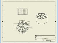
I've been trying that too, I don't have enough space between the motor. I even tried to design a set up where the can itself had gears attached, but no dice :p
But the idea is good, the problem is that I was too greedy with the idea of building a narrow and small frame. No room for anything :roll:
 
I've been drawing a rear frame in sheet aluminum and I think I have the design that I like and is possible to make without too much hassle.
The great advantage I have with drawing it as sheet metal in Inventor is that I can export every single parts as a flat 2d drawing with bend details and everything I need.

I know 3-d drawings are boring to see, but it will be fun when I have all the parts made :D
 

Attachments

  • Rear frame.jpg
    Rear frame.jpg
    19.2 KB · Views: 3,109
I also managed to slim down the drive pulley from 600g to 265g with a couple of holes :)
Both pulleys will be lighter than one stock, but they are still heavy as a pig :p
I wonder why they don't make them in aluminum, only from 40t on upwards
 

Attachments

  • Motorpulley lettet.jpg
    Motorpulley lettet.jpg
    39.9 KB · Views: 3,066
Hello

I've been working a bit this weekend, but things are going slower than I thought it would. What you see took too much time, and I still have a lot more to do.
Much time was spent just getting rid off excess material, and I hope to make more progress soon.
 

Attachments

  • IMG_7461.JPG
    IMG_7461.JPG
    72.8 KB · Views: 2,899
  • IMG_7495.JPG
    IMG_7495.JPG
    101.6 KB · Views: 2,899
  • IMG_7491.JPG
    IMG_7491.JPG
    70.1 KB · Views: 2,899
  • IMG_7488.JPG
    IMG_7488.JPG
    48.6 KB · Views: 2,899
  • IMG_7477.jpg
    IMG_7477.jpg
    70.7 KB · Views: 2,899
  • IMG_7473.JPG
    IMG_7473.JPG
    46.4 KB · Views: 2,899
  • IMG_7471.JPG
    IMG_7471.JPG
    49.5 KB · Views: 2,899
  • IMG_7469.JPG
    IMG_7469.JPG
    69.1 KB · Views: 2,899
  • IMG_7466.jpg
    IMG_7466.jpg
    77.6 KB · Views: 2,899
  • IMG_7500.JPG
    IMG_7500.JPG
    51.9 KB · Views: 2,899
Hello boys and girls,

Today was the first day working at a school's mechanical workshop near where I live. They actually had pretty good equipment, so I had a pleasant experience.
I made two motor mounts, they are slimmer and have the mounts for the bolt pattern spread wider than the original mount.
The mounts are made so the support bearing automatically will be centered since the motor mount and support bearing have the same bolt pattern.

Here's a few pictures of todays work, slowly but steady ;)
 

Attachments

  • IMG_7513.JPG
    IMG_7513.JPG
    71.1 KB · Views: 2,799
  • IMG_7512.JPG
    IMG_7512.JPG
    71.5 KB · Views: 2,799
  • IMG_7518.JPG
    IMG_7518.JPG
    77.2 KB · Views: 2,799
  • IMG_7519-001.JPG
    IMG_7519-001.JPG
    85.4 KB · Views: 2,799
  • IMG_7520.JPG
    IMG_7520.JPG
    70.4 KB · Views: 2,799
  • IMG_7521.JPG
    IMG_7521.JPG
    66.3 KB · Views: 2,799
hers a my post of a moded mongoose frame
http://endless-sphere.com/forums/viewtopic.php?f=6&t=47452&start=100#p724109
file.php

its steel but yeah, its rediculously tough :) 2mm sheet bent into channel and end platets welded in and cut and welded into frame with gusset / brackets.
EDIT: PS
that looks SICK!
file.php
 
SICK?
thats a really cool "bomber style" frame
 
pendragon8000 said:
hers a my post of a moded mongoose frame
http://endless-sphere.com/forums/viewtopic.php?f=6&t=47452&start=100#p724109
file.php

its steel but yeah, its rediculously tough :) 2mm sheet bent into channel and end platets welded in and cut and welded into frame with gusset / brackets.
EDIT: PS
that looks SICK!
file.php


Nice work, shoud ride very well :)
Yeah, steel is strong and forgiving, especially for me who don't know how strong certain parts of the frame needs to be.
 
dh-paule said:
SICK?
thats a really cool "bomber style" frame

Thank you, appreciate it :p

In reality, the frame is just a copy of a big hit frame. It is just a coincidence that the bomber is almost the same.
I think most would designers would make something like the bomber frame if making a electric dh bike was the goal.
It's just a general design that pretty much every simple-to-make boxed frame would look like.
 
How your build going I had a test ride on mine with old 48v headway pack. Had 10v sag lol still flipped as go no rear brake yet. Lol want more power
 
I have now seen one of these motors running 42v ... :twisted: you are creating a monster ,cant wait to see this running its ganna be awsome
 
More work is done, I think it will work out just the way I thought.
I am finished with two new motor axles in stainless steel, hope they are hard enough. Better than the original butter steel at least :D
I also got the support bearing holder done, only need the last finishing touches, but I won't waste preciouses work time on details just yet, that I can do without any fancy equipment anyway.
The next step is to make a way to tension the belt. I know how I want to solve the problem, and it's very simple and compact. I'm also happy that I don't need a tensioner pulley, they suck for energy and space.

Here's a bunch of more or less interesting pictures, enjoy :lol:
 

Attachments

  • IMG_7549.JPG
    IMG_7549.JPG
    58.7 KB · Views: 2,516
  • IMG_7550.JPG
    IMG_7550.JPG
    73.9 KB · Views: 2,516
  • IMG_7553.JPG
    IMG_7553.JPG
    68.9 KB · Views: 2,516
  • IMG_7554.JPG
    IMG_7554.JPG
    75.5 KB · Views: 2,516
  • IMG_7546.JPG
    IMG_7546.JPG
    56.8 KB · Views: 2,516
  • IMG_7548.jpg
    IMG_7548.jpg
    63.8 KB · Views: 2,516
  • IMG_7556.jpg
    IMG_7556.jpg
    71.5 KB · Views: 2,516
  • IMG_7544.JPG
    IMG_7544.JPG
    74.3 KB · Views: 2,516
  • IMG_7541.JPG
    IMG_7541.JPG
    75.3 KB · Views: 2,516
  • IMG_7538.JPG
    IMG_7538.JPG
    55.8 KB · Views: 2,516
  • IMG_7527.JPG
    IMG_7527.JPG
    62.1 KB · Views: 2,516
  • IMG_7530.JPG
    IMG_7530.JPG
    61.9 KB · Views: 2,516
  • IMG_7531-001.JPG
    IMG_7531-001.JPG
    64 KB · Views: 2,516
  • IMG_7532.JPG
    IMG_7532.JPG
    92.3 KB · Views: 2,516
  • IMG_7533.JPG
    IMG_7533.JPG
    83.8 KB · Views: 2,516
  • IMG_7534.JPG
    IMG_7534.JPG
    69.1 KB · Views: 2,516
  • IMG_7536.JPG
    IMG_7536.JPG
    60.3 KB · Views: 2,516
pendragon8000 said:
where the swing arm you had desighned? getting there? must be allot of work fabing all the gear box stuff and well prety much everything.

My school just got the gas fir the tig refilled, so I am about to start practicing my welding skills. I got the hang of welding steel and stainless, but aluminum is tricky. But it's just a matter of time ;)

I will make the swing arm when I feel that the welds are good enough
 
Idontwanttopedal said:
How your build going I had a test ride on mine with old 48v headway pack. Had 10v sag lol still flipped as go no rear brake yet. Lol want more power

Nicely done, I guess you had a great time testing the bike? I have done the same, too easy without a good rear brake :x
 
dustyearlobe said:
I have now seen one of these motors running 42v ... :twisted: you are creating a monster ,cant wait to see this running its ganna be awsome

I need a monster to satisfy my needs 8)
What isn't better then being able to get a rush every time the throttle is pulled? I hope to make a reliable bike that can take a pounding without breaking.
 
A little more is done, just a few more parts and I can finally drive the bike again.
Spring is coming to Norway, and I love the smell and all the new noises that comes with the warm weather. Especially the sound from two wheeled bikes :D
I can feel the rush just by listening in the evenings, and my body tells me that it is time to push the limits again. I have a need for speed 8)

Anyway, I took a couple of pictures so you can see the progress. I have been able to mount both motors and pulleys. It seems to line up well, but I have to make a new axle for the driven pulley before I can test. I also need a couple of 4x4x28mm keys for the motor pulleys.

I had a few moments of total happiness when I managed to get the clips and dimples in the motor axles lined up perfectly. I cant explain how good it is to see that all the measurements is bang on :lol:
 

Attachments

  • IMG_7574.JPG
    IMG_7574.JPG
    77.8 KB · Views: 2,403
  • IMG_7572.JPG
    IMG_7572.JPG
    77.4 KB · Views: 2,403
  • IMG_7570.JPG
    IMG_7570.JPG
    87.9 KB · Views: 2,403
  • IMG_7567.JPG
    IMG_7567.JPG
    85 KB · Views: 2,403
  • IMG_7566.jpg
    IMG_7566.jpg
    58.6 KB · Views: 2,403
  • IMG_7564.JPG
    IMG_7564.JPG
    73.1 KB · Views: 2,403
  • IMG_7559.JPG
    IMG_7559.JPG
    76 KB · Views: 2,403
  • IMG_7558.JPG
    IMG_7558.JPG
    74.6 KB · Views: 2,403
  • IMG_7557.JPG
    IMG_7557.JPG
    70.1 KB · Views: 2,403
  • IMG_7577.JPG
    IMG_7577.JPG
    81.6 KB · Views: 2,403
Back
Top