Doctorbass said:
You did a VERY clean and nice job!!! :wink:
Congrat!
Q1: Can you describe what is your feeling when switching from 5304 to 5302?
like a runner getting his second wind. in 5304 mode using 48V it would pull reasonably hard up to 20kph and start running out of steam at 25kph. switch to 02 mode and it would continue to pull hard up to 45kph. after 45kph it would still accelerate, but not as quickly. remember i was using 48V 33Ahr SLA batteries.
Doctorbass said:
Q2: Had you ever experienced some fear about the danger of switching back to 5304 when you are at full speed? ( the back EMF is alot higher than the controller speed... since you accelerate using 02... then 04... then stabilize then switch back to 04...

you actually slow down when switiching from 5302 to 5304. just like mild regen braking. the high voltage and speed dissipates quickly. it is a very transient thing. just like in a car you learn not to downshift from full speed. roll off the throttle, slow a bit and then flick the switch for 5304 mode.
the controller was an analog Crystalyte V1 - 12fet with 4110 mosfets. the limit was set to 50A by modifying the error amp. in practice it worked out to closer to 60A. but with the SLA batteries i could draw the 50 - 60A at full voltage for only a short period of time hot off the charger. after a few minutes at high current draws the voltage would sag down to 40V limiting the available power. the combination of 100V fets and limiting the battery to 48V i did not think that i would nave a big problem. and i didn't.
Doctorbass said:
Q3.. Are these relay spdt? or normal spst? where do you got them?.. ( I actually have 10 SPDT of the same size BUT rated 70A..!)
did you measured the KV difference or no load speed difference for each mode?
Great find about not using plastic tie rap and replacing bu something that hold better high temp!
i never measured the Kv it was more of a seat of the pants thing in those days. the relays are SPDT. i bought them as a liqidation item on eBay. but it sounds as if you have better relays.
Doctorbass said:
Q4: What is the max peak and continuous power did you used with it?
peak power was over 2.9Kw according to the old Drain Brain i was using then. it was the latest thing when i was using it though. that was during hard acceleration. average power while cruising around the track was 750W. in electrathon the idea is to see how far you can go using 73lbs worth of SLA batteries. you want to keep the motor running in a peak zone.
Doctorbass said:
Q5: When you say you re-wound this 5302, do you mean you really removed the winding and re-wound it by yourself with all the patience it need?? or that you just reconnected or divided the winding seperate phase wire into different group for parallel-serie?
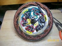
the one in the pictures was actually rewound. after i had baked it and sheared off one side i had one of those miraculous visions. like long past the point of no return. i realised that the 5302 used 8 strands of wire. if i separated them and isolated them into 2 sets of 4 wires each.... the second motor was done that way.this was done back in 2005/2006 before my accident. after the accident i lost my rented workspace. not having anyplace to keep them, the second motor and the frame were donated to a local school for them to use. the did use the frame but with a different motor. that motor is MIA. i wish i knew where it ended up.
Doctorbass said:
Q6: could you try it on a 5303 or 5304? if not.. why is it possible?.. I mean cuting the 5304 winding from 3 group to 6 group is not fesable?
i don't see why not. last year, when we traded my 5302 (that you used on your infamous drag strip run) for your 5304 that was the first thing that came to mind. making a 5308/5304. but i was concerned about the powerful cogging/ vibration at low rpm in 5308 mode. definitetly need torque arms for that.
in your case a 5306/5303 might be a better drag racer. but only if you could find relays adequate to the task that would still fit inside the case. 150A is a lot of carrying current. but the low speed coging of the 5306 would be rough but acceptable.
Doctorbass said:
Again... i must say.. You did a great job!
Doc
thanks,
rick


")