Emmo Knight (Grom clone) salvage

A weekend of beautiful weather was a good excuse to go for a rip.

IMG_20221022_141317719_HDR.jpg
IMG_20221022_141333395_HDR.jpg
IMG_20221022_141344875_HDR.jpg

Just to see how it feels, I've turned the max battery amps up to 325A from 235A and it is noticeable. I realize I need more phase amps though... next year I may go for a bigger controller but the 530A (440 real world) phase is still enjoyable.
 
A new seasons of riding is here and ... I'm still not ready (soon though). The upgrades and fixes are still underway. I'm doing a couple simple things like replacing the horn I accidently cooked with full battery voltage instead of 12V. The perfect item to get on aliexpress for less than $3 CAD:IMG_20230419_192042458.jpg

I'm also trying to replace the missing rubber cushions for the seat as seen here. The are the same as a Honda Grom, but I didn't want to pay Honda Grom part prices:

IMG_20230215_123121124_HDR.jpg
I'm going to use some of these (also from Aliexpress) for the rectangular ones:
Hcb47e7781a2149a1a1b3fc82c03a85a22.jpg

And some of these for the round ones:
Haad029a301c049729f004627f3020abbF.jpg

I'm planning on securing the rounds ones with well nuts that will expand inside the hole in the seat as the bolt is tightened:
Sbf1239e2c8d341aeb48ad59552acd365D.jpeg
 
The rubber bob for the seat have arrived and installed nicely; the seat seems more secure now on the bike. I only added the missing ones but I may replace all of them so that both sides match.

And now for some more exciting upgrades...

a brand new 3Shul CL700 motor controller (VESC based) that is rated for 700 phase amps and up to 30S lithium ion. I will be sticking with my 24S pack since it's working nicely:
IMG_20230417_150043565_HDR.jpg

More info and progress to come.
 
After a couple hours planning how/where to mount the controller; I've settled on this; which should be good for airflow (but poor crash resistance) and have clearance for the rear mud-guard when bouncing around. I used some scrap steel from a bed frame, which works out fairly nicely with rounded corners.
IMG_20230418_192302134_HDR.jpg

After some paint/primer on the controller bracket:
IMG_20230429_100926090_HDR.jpg

I've also decided to put all the controller connectors under the seat for more protection and a cleaner look than I had before. I'll be cutting a hole here and stuffing everything in:
IMG_20230418_192310086_HDR.jpg

There is still hours of work ahead; but it will be mostly tuning and smaller things I think. IE: I have to change where the battery cables exit the frame; luckily for me they will still be long enough and I can keep existing terminals (lugs). I'm excited to get to know the VESC tool; it is leagues ahead (and open source) of any other software I used for programming a controller; including many parameters that are far beyond my current technical understanding.
 
I'm excited to get to know the VESC tool
Super nice build, I think you are going to end up loving the VESC ecosystem.
Benjamin Vedder and all the too-numerous-to-mention contributors of software/hardware, have really done the community a solid.

If you run into problems setting up the 3Shul, BenV and hackey(3Shul) frequent the VESC development Discord channel.
To facilitate sharing knowledge on the 'sphere, Discord link:
Join the VESC development Discord Server!
 
The holes were cut for the cable harness to fit under the seat:
IMG_20230419_124924249.jpg

These connectors seem pretty nice; much better than most I've used on budget ebike setups etc... This particular one is for the throttle and variable regen:
IMG_20230420_183933559_HDR.jpg

here is what the controller looks like from the other side. It should have enough clearance and there won't be a bundle of connectors hanging out near the spinning wheel like I had before:
IMG_20230419_124932900_HDR.jpg

Re-routing battery cables and motor harness. The motor harness will be secured as seen in the photo but the battery cables will get moved to the other side of the bike:
IMG_20230419_182945247_HDR.jpg
 
I had 3shul motors setup the controller for me remotely; the amount of technology I had going at once during the tuning process was something to see. I had to use a mobile phone to allow my laptop computer to connect to the internet (wfifi not working on laptop), the mobile phone was also connected to the vesc controller via Bluetooth. The phone was used as VESC Tool tcp bridge from the controller to the laptop and 3shul remotely accesses my laptop and did all the tuning from there....

IMG_20230415_130754822.jpg

I did a few short test rides to uncover the first few hiccups with the controller configuration. The variable regen braking was there but cutting out and choppy. Hard accelerations were causing the controller to cut out/power to dip down (but not throwing a fault). I was also having an issue a few days later with the throttle/regen brake no longer working. Being new to vesc, I definitely felt a bit over my head.

Fast forwarding about 1 week or so and I now have all the issues resolved thanks to the excellent customer service from 3shul motors (I'm assuming I was speaking with Hackey). (y)

For some reason the ground pin for the throttle/regen/motor halls was no longer working; so I by passed it and connected it to the ground pin for the sin/cos encoder plug (not in use). The other motor behaviors were all solved from tuning the controller. The motor accelerates hard without cutting out and variable regen braking is working down to fairly low rpms. The VESC Tool is definitely the best controller software I've used; logging is a great feature to help understand how the controller/motor is behaving.

I will be doing more riding and trying to fine tune some of the controller features in the future. I also need to keep working on my DIY display that will communicate with the VESC / 3shul controller but it is taking a long time. All I've got on my current display is battery voltage since this display is meant to attach directly to each signal cable (for speed, temp, voltage etc...). The new VESC display I'm working on will pull all the data from the controller so I don't need to feed it pack voltage and an analogue speed wire etc..


20230511_124836.jpg
 
Do you have regen on the throttle or a separate input? Did they use the Wizards to auto tune the motor or did they set everything individually? It would be interesting to see your settings.
I've got regen on a separate input from the throttle. I believe they set everything manually; there are a couple detection buttons that were used in the FOC section that measure Resistance, Inductance and Flux Linkage. Most of which is beyond my understanding at the moment but it is good to have such technical parameters; so I can eventually learn about each one. Here are some setting on the General tab of FOC that were used; I will try and get an export of every parameter so you can see.
 

Attachments

  • vesc_qs26050H.png
    vesc_qs26050H.png
    45.8 KB · Views: 3
Last edited:
Keep an eye on those torque arms! Regen with non clamping dropouts can cause the axle to rock back and forth in the flats of the torque arms, wearing either the axle or the torque arm out, depending on which is softer. If the axle spins, you could shred your phase wires and damage anything they are connected to.
 
Keep an eye on those torque arms! Regen with non clamping dropouts can cause the axle to rock back and forth in the flats of the torque arms, wearing either the axle or the torque arm out, depending on which is softer. If the axle spins, you could shred your phase wires and damage anything they are connected to.
Thanks for the warning. I have been checking them to make sure they were tight; but haven't done so the last few rides; a good reminder.
 
Nice :bigthumb:
We were supposed to set up my controller yesterday, but it seemed like something came up for Hackey so he wanted to move it to today instead. But today I got home late so I wasnt able to get in touch with him.

They have a youtube video on how to set up the motor parameters, so I suppose that is how they did and not use the wizards.
 
For those interested, here is an export of my 3shul/ VESC controller / app parameters working with the QS260 50H v4 hub motor shown in this thread.
 

Attachments

  • vesc_mcconf.xml
    10.4 KB · Views: 6
  • vesc_appconf.xml
    11.8 KB · Views: 3
I am building my own display for this bike. I've got many hours just getting it to work (wiring, and research which code libraries I want to use) but here is an early photo of my Pie Pico + 3.5 inch TFT communicating via UART to my ANT bms and some TFT tests using Bodmer's tft e_SPI library. Will be updating will some more progress photos.
 

Attachments

  • IMG_20230310_112326974_HDR.jpg
    IMG_20230310_112326974_HDR.jpg
    2.3 MB · Views: 7
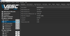
I had some more testing while trying to get the Pico to communicate with the VESC / 3shul. There are many connections from the Pico to the display module since it uses a 16 bit parallel interface. I ran from the shop back to the computer at lease a dozen times since I was doing the programming in a different space.
IMG_20230604_141555172_HDR.jpg

My plan was to fit the screen + cables + Pico inside the original display housing to hide the rats nest of cables etc... Here is what the housing looks like disassembled. Pretty cheap plastic with screws instead of bolts. I wonder how different the Honda assembly would be?
IMG_20230605_163212431_HDR.jpg
IMG_20230605_163216994_HDR.jpg

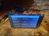
Finally, I got the VESC and Pico talking. That took many hours of code debugging, even though I was using libraries written for the job. There are many sections of code to get working, even getting a larger font included and working took time. It doesn't look bad in the photo but my first test ride with this didn't work too well... the display was nearly impossible to see between the deep scratches on the cover and the reflecting sunlight (photo taken indoors).

IMG_20230604_185449228_HDR.jpg


Back to programming I went. After doing some research, it seems that the ideal colour combo on a TFT for sunlight is black text on a white background because the light reflects off of the black more than white. For some reason, the display was now cutting out and just showing a white screen after a few seconds. I probably spent another 6 hours or so troubleshooting that. In the end, it turned out that I needed more ground connections from the display to the Pico; strange that it wasn't doing it with the black background but I supposed the connection got weaker from me plugging and unplugging those small header connections.

You can see it looks better in the photo but sunlight is still a problem, even demonstrated in the second photo from a different angle.

IMG_20230609_175145180_HDR.jpg

IMG_20230609_175153255.jpg

I've got the display working as well as I can get it, at least I can see my speed *some* of the time now. I have a few more tweaks to it that I'll be posting next.
 
Last edited:
With the 3shul controller running pretty well for me (still want to do a bit of tuning for some more low rpm acceleration), the motor temperature tells me that the QS260 50H is now the more under-sized component on this bike. That's OK, I usually have a weakest link somewhere in the setup as I experiment with components.

Having had success in the past with Statorade, I decided to "why not try it" for this build too. One order to Grin and a week or so later; I have a 50ml bottle of Statorade.

After removing the motor from the bike and documenting which washer goes where, It was time to open it up. The cable side cover came off fairly easy, but I did have to use a couple pry bars to break the seal of factory blue goo (Silicone maybe?).
IMG_20230612_123002612_HDR.jpg
IMG_20230612_123006852_HDR.jpg

I cleaned off all of the factory sealant from the motor side cover and rim. I opted for approximately 20mL of Statorade, used the syringe to apply a small amount to each magnet. I sealed the side cover back up with some black RTV sealant that I've used for two other hub motors in the past.

I also wanted to "tone-down" the orange motor cable harness; to try and blend in more with the factory ebikes around here. What a job that was. I had to fit a large length of thick heat shirk tubing over the connectors etc... the tubing barely fit over the connectors and I had to tape them up to make the tubing slide over a bit easier... I put all my might into pulling the tubing down the cable harness taking breaks in between. I probably took me a solid 20 minutes of tugging on the heat shrink while making sure it slid over the connectors. I then shrunk the tubing with all the heat my heat gun could throw... even after shrinking the tubing was just a tad too big but good enough for the job.

Here is a shot half way through the shrinking:
IMG_20230613_114329677_HDR.jpg

Too be continued...
 
Did you consider split loom?
I did, but I wanted a "smooth" looking surface on the motor cable.


To continue where I left off... I tried to get away with sealing only one side of the motor and relying on the factory silicone or whatever they use. That was a mistake. After a couple rides, I could see a bit of Statorade leaking from the side cover:
IMG_20230618_165633609_HDR (1).jpg

I wrestled with the removal process of the side cover. The air valve was also making things difficult:
IMG_20230618_193807175_HDR (2).jpg

I went around the side cover and pried up with some pry-bars; which I have done in the past with success on other hubs but this motor + rim had poor angles for getting the prybar in a good spot. I thought I may be missing a circlip / snap ring that I had to remove? After a good while of frustratingly trying to get the cover to come off; I ended up using a gear puller attached to the disk rotor. My gear puller wasn't long enough so I have to get a bit more creative with it but it worked. Here are a couple shots of the disk side of the motor with the cover off:
IMG_20230619_120101808_HDR.jpgIMG_20230619_120108375_HDR.jpgIMG_20230619_120124529_HDR.jpg

I did a bit of damage trying to pry that cover off and separated a couple of the outer laminations... :sick: Now I know to go straight to the gear puller after breaking the seal.

I cleaned up the rim and the cover, topped up the motor with a few mL of Statorade and sealed it back up. I also took the opportunity to drill a small hole in the side cover so I can top it up without removing the motor from the bike. I was very worried the motor might act up after the prybar vs lamination mishap but am happy to report the motor is working fine and the Statorade is doing it's job with no more leakage.
 
As long as the windings aren't damaged, there can be some significant lamination damage and the motor will still work fine (might not be quite as efficient as original, but you probably wouldn't notice).
 
  • Like
Reactions: pwd
I noticed one of the brake levers was getting squishy and loosing braking power. Upon inspection I found the fluid reseviour was leaking fluid from the clear inspection window:
IMG_20230613_202440049_HDR.jpg

After poking the inspection window on the other side's brake fluid reservoir; it started leaking too. I had just bled the brakes a couple weeks ago too. O well.

I ordered some new master cylinders/levers from Amazon (so it would get here quick) and they bolted right up. I had to swap over the brake sensor switch on each one but it pretty much bolted right in; another plus for cheap generic parts. I re-bled the system and was back on the road. One of the new brake levers was slow to return; so I ended up taking it apart and re-assembling and the problem hasn't come back.

New brake levers installed and working. Photos were taken a while back, when there was wild-fire smoke in the air (enough to choke):

IMG_20230625_084126093_HDR.jpg
IMG_20230625_084138176_HDR.jpg
 
Back
Top