End turns bad?

Buk___ said:
...
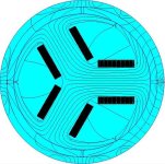
The motors we use have much more complex topology, and far more complex and contained magnetic circuits. Something like this (simulated on a similar 100mm diameter scale to the wire loop motor simulation above):
4pole3toothMotorMagbeticCircuits.jpg
4pole3toothMotorMagbeticCircuits.jpg

Perhaps you can elaborate on this simulation of a motor, as you say, having "much more complex topology, and far more complex and contained magnetic circuit". For instance, is it a 3 phase BLDC? Also, do the lines represent flux from 4 magnets? Is this design and simulation your handiwork or from elsewhere? Does a real model (hardware) exist? Why did you decide to post it in a reply to my post concerning end-turns and effective armature conductor length? Thanks in advance.

major
 
Buk___ said:
major said:
No motion of magnet or coil. And can be very strong. Often is the maximum torque for a motor.
Sorry, but that contradicts everything I've read.
??

A stationary solenoidal coil produces a magnetic field when current passes through it. The H-field is determined by the geometry of the coil and the amp-turns; the B field is determined by H field and average permeability of the surrounding magnetic paths.

A permanent magnet creates a stationary magnetic field.

The interaction of these two fields produces torque in a motor, whether it is stationary or spinning. Commutation then ensures that the torque is always applied so as to rotate the motor in the desired direction. Maximum torque is limited by the maximum current the windings can take without overheating, and at higher speeds by the maximum potential the inverter can generate to overcome back-EMF. Practically maximum torque often comes at minimum speed since there is no back-EMF at minimum speed; this means current is at maximum in a non current limited system (and maximum current is available on current limited systems.)

That's basic rotating machines. Some motors impose additional limits due to their construction (i.e. maximum currents in a commutator) but those are secondary to the fundamental forces working within the machine.
 
major said:
Buk___ said:
...
The motors we use have much more complex topology, and far more complex and contained magnetic circuits. Something like this (simulated on a similar 100mm diameter scale to the wire loop motor simulation above):
4pole3toothMotorMagbeticCircuits.jpg

4pole3toothMotorMagbeticCircuits.jpg

Perhaps you can elaborate on this simulation of a motor, as you say, having "much more complex topology, and far more complex and contained magnetic circuit". For instance, is it a 3 phase BLDC? Also, do the lines represent flux from 4 magnets? Is this design and simulation your handiwork or from elsewhere? Does a real model (hardware) exist? Why did you decide to post it in a reply to my post concerning end-turns and effective armature conductor length? Thanks in advance.

major

It's the simplest, 3-phase BLDC topology (that I know of), and it is loosely based on a simple case fan motor scaled up. The actual motor I based it upon went in the bin because I broke the circuit board getting the rotor/blade off (a few weeks ago). It was never going to run again. I still have the magnet.

Yes. The lines represent lines of equal flux -- in Tesla -- but in addition to the fields from the 4 magnets, I believe that 2 of the phases were excited, but I don't recall which coils, or which direction and level of current was flowing when I took the screen grab. I posted it because the simulation run happened to complete as I was constructing my reply to you and it made my points about topology and field complexity.

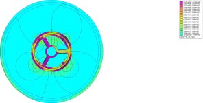
Here is the latest iteration of that motor:4pole3phaseV+-W+-excited.jpg

You'll see that it has simplified further -- the coils are much smaller now -- because with a realistic number of conductors per coil, the simulation runs were taking days and even screen redraws took 20 minutes.

The reason for modelling the conductors individually rather en-bloc, is so that I could examine the Lorentz forces affecting each individual conductor; to allow me to document the low level of torque they generate, the way it falls off rapidly with the distance of the conductor from the magnet; and that the torque produced by the conductors on one side of a tooth (almost) exactly counterbalance that produce by the corresponding conductor on the other side.

How, if a BLDC motor relied entirely upon Lorentz force for torque, it would produce little or none; because for every position of the rotor where the flux imbalance across the tooth was such that net Lorentz force generated by the two activated teeth was positive, there is another position within the same revolution where the net balance is the exact opposite.

It was then -- and only then -- that it dawned on me that it didn't matter. That no amount of torque from the windings attached to the stator could possibly cause the rotor to rotate. You postulated that Newton's 3rd might be a possibility, but that defines that when the cannonball is launched, the cannon moves backward in reaction; it does not define what forces are involved when the cannonball lands.

Having produced a model that is realistic enough to satisfy the "would it really run if built question"; and simplified enough that it completes in a realistic amount of time (~15 minutes), I'm currently writing a script to rotate the motor through 360 1° steps, commutating the phases and gathering the individual and net Lorentz torques, as well as the net torque acting on the rotor (via weighted stress tensor) and taking plot grabs to assemble into a movie. (It'll take me a while as my LUA is very rusty.).

-------

Bringing it back full circle:

One of the reasons given for end turns being bad, is because they do not contribute torque because they are oriented wrongly for a Lorentz force to act up on them. I conclude that this is a misnomer for the reasons given above.

Another is that they do not contribute to the flux in the core. This (IMO) is equally, obviously wrong. The fact that the solenoid is square or rectangular doesn't prevent the current flowing in all parts of the conductor contributing to the flux in the core; neither the current nor the flux know the core isn't round, nor what side of it they are on.

And another is that they waste power through "flux leakage". Whilst it is easy to detect flux outside the core around the end turns -- whether in axi-symmetric simulations or with that plastic flux film on a real motor; it is (IMO) a misnomer to consider it "leakage". One of the fundamental tenants of the "lines of flux" according to the Amperian model, is
magnetic B-field lines neither start nor end (mathematically, B is a solenoidal vector field); a field line either extends to infinity or wraps around to form a closed curve

Flux lines are loops, and the flux lines detected outside of the tooth core are the return halves of flux lines running within the core -- the other halves of the closed loops can be nowhere else given the proximity of the coils to the cores they surround -- so they are contributing to the flux density within those cores.

The fact that the flux density within the cores is so high that some of the flux lines find the path of least resistance through the air rather than the core and back-iron, means the core must contain a dense field.

The fact that you get no eddy currents induced in air means that the leakage flux isn't wasting power that way.

All of this seems very clear and logical to me; despite that I know it does not fit with the simple textbook models; or many people's learning based on those texts; but I've yet to see (or possibly yet to appreciate) any thing that shows me (rather than just tells me) that my logic (and modelling) is wrong.

I will continue to model, and research and if I find the means and resources, physically test until I find definitive evidence; for or against.

I will (Gatekeeper permitting) continue to discuss and debate anyone who feels inclined to reason with me (for which you and AlanB have my profound thanks).

If no one chooses to engage with me, I'll stop posting; but my quest to arrive at a level of understanding where I no longer have a bunch of nagging doubts that I cannot resolve; with the aim that I can design a motor in theory, and have a good chance that if I stump up the cash to build it, it will work, will continue.

Thanks for your having taken the time, Buk
 
billvon said:
The interaction of these two fields produces torque in a motor, whether it is stationary or spinning.

You missed the context in which that was said.

Major suggested that Lenz Law might be a way for the physical Lorentz force acting on a conductor in the static stator, to feedback and apply torque to the remote rotor.

But Lenz Law requires that the magnet be moving (and moving to or fro on the axis of the coil), in order to induce a current that flows in the opposite direction the current already existing.

I was pointing out that If Lenz Law was the way Lorentz force was transmitted from stator coil to rotor magnet; then there could be no torque produced when the rotor was stationary.

It was proof by contradiction: Electric motors produce torque from stall; Lenz Law require the magnets to be moving; thus Lenz Law cannot be the source or cause of torque at the rotor.
 
It may help in the above diagram 3 pole rotor with 4 pole stator to indicate N S poles of all parts and bear in mind the attractive and repulsive forces of each as it contributes to total torque in the rotor as well as the Magnetic field strength of each of the three poles in the rotor since it divides on the left side as it passes the central shaft. I know I get confused when the stator and rotor have different numbers of poles which I assume is done to reduce cogging but adds to the complexity of the calculation for torque since how much each pole contributes is not equal and becomes a function of their angle of rotation relative to the stator poles they are interacting with. Geezzz I am aquiring a deeper understanding of this than I ever expected. My brain is starting to get full!
From a programming perspective I can give you this one piece of advice, make sure you have the sign (+/-) correct when adding up totals taking into account which side of the rotation axis you are on and what side of the core tooth you are on.
Sometimes the old textbooks were just wrong ...too!
 
JanComputerman said:
It may help in the above diagram 3 pole rotor with 4 pole stator to indicate N S poles of all parts

The simulator has labels for all the part that shows the direction of magnetisation of the magnets; and the polarity of the current in the coils. I have them turned of because with so many small conductors so close together, the text all overlaps and creates a big black splodge :)

JanComputerman said:
I know I get confused when the stator and rotor have different numbers of poles which I assume is done to reduce cogging

The poles needs to be an even number so that they go N-S all the way around. The teeth needs to be a multiple of 3 because its 3-phases.

JanComputerman said:
but adds to the complexity of the calculation for torque since how much each pole contributes is not equal and becomes a function of their angle of rotation relative to the stator poles they are interacting with. Geezzz I am aquiring a deeper understanding of this than I ever expected. My brain is starting to get full!

I know that feeling :)

JanComputerman said:
From a programming perspective I can give you this one piece of advice, make sure you have the sign (+/-) correct when adding up totals taking into account which side of the rotation axis you are on and what side of the core tooth you are on.
Sometimes the old textbooks were just wrong ...too!

Thankfully, the simulator software does all the calculations and keeps track of the signs; all I need to do is add them -- provided I program the commutation sequence and rotation correctly.

The hardest part is discovering and working around the limitation of the sim software. For example, it uses floating point for its coordinates, which means that if you rotate the magnets by 1 degree each time, rounding errors accumulate; and if you have small gaps between rotating and non-rotating parts -- eg. 0.25mm air gap between magnets and stator -- they can accumulate to the point where the parts start overlapping.

The software doesn't differentiate between programmed model changes -- like rotations for analysis -- and model changes done manually when constructing and editing. So, if parts overlap, it creates new nodes where lines cross and at the next rotation one end of those lines move, and the other at the new node stays stationary, they rubber band, which inevitably creates more collisions and more new nodes and results in an unholy bloody mess.

(You learn early to make sure you have a back up of the model before you run a script on it, because any changes made to the model during a script run become a permanent part of the model file!
 
Buk___ said:
I also do not take things as read without questioning stuff, until my own understanding gells with received wisdom, or surpasses it.

I certainly don't hang on the coat tails of others -- John was right, Miles was right, Major was right -- especially when in two out of 3 of those cases, they weren't.

Nor do I follow people around from thread to thread, posting non-contributory "how dumb are you that you had to ask that question"; and when challenged, construct a character assassination piece in a fit of pique.

Calm down, dear. I know it's uncomfortable to have examples of one's ignorance highlighted while one is busy questioning the competence of others on similar subjects, but that's life. A standard component of further education is training to assess the quality and veracity of potential references (sources). I am pointing out here that you fail this test for a number of reasons, one of which are the quality of your prior utterances. Therefore your explanations of how a motor works (or apparently, cannot work, it seems) fall far below those of the authors you have dismissed as plain wrong.

To put a fine point on it, if I were researching how a motor operates I would rank your posts probably as reliable a source as youtube comments and would not dare cite them. If I were running a project that involved hiring a consultant to design a motor, you would not get the job. I'm not saying there is no chance you are right, but it is unlikely.

I only say this to help you as I think it would aid your understanding to temper your opinion of your own abilities and be more opening to sources of knowledge. "Received wisdom" is often used pejoratively and this seems to reflect your "challenge everything" attitude and ambition to "surpass" it. This is well established physics you assume to dismiss.

Buk___ said:
I will continue to model, and research and if I find the means and resources, physically test until I find definitive evidence; for or against.

I will (Gatekeeper permitting) continue to discuss and debate anyone who feels inclined to reason with me (for which you and AlanB have my profound thanks).

Then I would suggest you un-ignore LiveForPhysics' suggestion of a simple experiment measuring the torque required to cog over a motor with single powered coil. It could be easily conducted in an afternoon using only a scrap motor core.

As an aside I'd say it's nice to see express some respect for those who have given their time to try and improve your understanding rather than just pointedly repeating "You're WRONG! You don't know what you're talking about, I know better", but I notice you are only extending your thanks to those who have not disagreed with you (note they haven't actually agreed with you).
 
Buk___ said:
... Lenz Law require the magnets to be moving; ...

I don't think so. The law addresses a changing current in a conductor or coil. When viewing web explanations or textbooks, often an illustrated example is seen using a moving magnet, but the law does not require a moving magnet.

major
 
Punx0r said:
Calm down, dear. ....

Then I would suggest you ...

Perfectly calm thanks dear. I'm immune to the inane attempts by small people to impose their will on others. But damn, that incessant mosquito-like whining can get irritating.
 
major said:
Buk___ said:
... Lenz Law require the magnets to be moving; ...

I don't think so. The law addresses a changing current in a conductor or coil. When viewing web explanations or textbooks, often an illustrated example is seen using a moving magnet, but the law does not require a moving magnet.

major

Lenz's law states that the direction of current induced in a conductor by a changing magnetic field due to induction is such that it creates a magnetic field that opposes the change that produced it.

Okay. So you are suggesting that the ramp up of phase voltage in the windings, creates a magnetic field around the conductor (per Faraday); and that rising magnetic field, (self) induces a current back into the same conductor that opposes the current that created it. And that affects the remote magnets.

But surely, that opposing current simply reduces or slows the rise in the phase current -- standard behavior for a inductor -- and reduces or slows the rise of the flux that phase current creates.

But any Lenz law induced current is (much) less* than the current that created it and it opposes it. So the field created by the original current is stronger, and more able to to affect (attract/repel) the magnets. And any affect the field created by the induced current would have would oppose the affect the original current is having. And it would be transitory, as is only occurs whilst the original current is changing, not once it hits steady state, and is proportional to the rate of change of that original current.

And what happened to Lorentz force?

And why do we need either? If Lenz law induced current can affect the magnets, then the much stronger field created by the phase current -- that which would be responsible for the Lenz law current -- can affect them direct, more strongly and in the desired direction.

I don't get what is wrong with 'phase current creates field, and that field attracts or repels the magnets'?

If you've got 4:18 to spare, watch this: this. No Lorentz, no Lenz, just Faraday.

*The induced current has to be less that the current that created the field that induced it, otherwise you have free amplification -- the original current self-induces a greater current, that would then self-induce an even greater current ... -- and that defies the conservation of energy.
 
Buk___ said:
Major suggested that Lenz Law might be a way for the physical Lorentz force acting on a conductor in the static stator, to feedback and apply torque to the remote rotor.
Sort of. All the Lenz law says is that any current you induce due to a changing magnetic field will always oppose the field. In this case that means that if you short the windings of a motor, it will be very hard to turn - because the current you induce in the coils will always oppose the magnetic field as it changes. That's true whether or not you already have a current flowing in that coil, due to superposition.

So the Lenz law will indeed contribute to torque of a stalled motor, but will not be the only effect. The larger effect will be the force between the field created by the windings and the static field of the magnets. In addition, the Lenz law is merely a description of one part of the effect of the rotating magnetic fields that make up a motor. In other words, it's the elephant's ear; it's not the whole elephant.

(Note that in an ideal motor with the turns shorted, there will be a tremendous amount of torque opposing any rotation - but you have to apply torque to see it. Whether or not you can measure torque without any movement at all is one of those thought experiments with no easy answer.)
 
billvon said:
So the Lenz law will indeed contribute to torque of a stalled motor,

But ... Lenz Law induced current and the field it creates, opposes the current that originated it and the field it creates, so rather than "contribute to the torque of the stalled motor", it would have to detract from it.

It could only contribute to it, if it was the primary source of the motive power in the direction of motion and overrode that opposite torque created by the phase current; but for it to do that would require the inverted amplification of the phase current, and that violates the conservation of energy, by creating some.
 
Buk___ said:
billvon said:
So the Lenz law will indeed contribute to torque of a stalled motor, 

But ... Lenz Law induced current and the field it creates, opposes the current that originated it and the field it creates, so rather than "contribute to the torque of the stalled motor", it would have to detract from it.

It could only contribute to it, if it was the primary source of the motive power in the direction of motion and overrode that opposite torque created by the phase current; but for it to do that would require the inverted amplification of the phase current, and that violates the conservation of energy, by creating some.

Bill's shorted motor turning exercise actually runs the machine as a generator. Understand difference between generator and motor.

Because you watch a video which explains the motor operation by simple magnetic attraction and repulsion doesn't refute the basic principles and laws, to some of which I have referred. Those still apply, as always. And they are not small or whimpy as to be ignored.

Yes you can do math and simulation. But what sense is there to find force on each of 20 or 30 conductors in air between bar magnets? That is never the case in a motor with a core and supporting magnetic structure.

As another member mentioned, you obviously do not understand basic principles so you claim them wrong along with those suggesting they could enlighten you as to the fallacy of your proposition that end turns contribute magnetically to torque production.

major
 
If I look back at post #1 of his thread, I think the problem is the precise definition of end turns.

As I see it (and I'm not a magnetics expert, though I did have the pleasure of working with some), anything wrapped around a tooth is part of a turn and contributes flux to the tooth (or anything contributing to the flux of the tooth is a good turn). Anything that departs from the tooth and heads off somewhere else is not part of a flux contributing turn. So perhaps that is the definition of an "end turn". It goes to the next tooth that needs to have that same current, and the flux it creates on the way is not directed in an efficient and useful manner. So this is wasted flux, and wasted I squared R loss. It might have some small effect in either a positive or negative direction, but it does not have the precise focussed permeability magnified effect of the coils around the tooth.

We had a similar problem in accelerator magnets. Our accelerator is a ring and many beam bending magnets need to have the exact same current in them, so they are connected in series. But this series wiring makes a coil of one turn going around the entire ring. This is an undesirable magnetic circuit, and even though the effect is very small, it is not zero (and the current in this water cooled cable was around 900 amps, the power supply was half a megawatt). The answer was to pair the conductor to cancel the field, which meant running the current all the way backwards around the ring after the last magnet, creating a large I squared R loss, and greater load on the water cooling for the cable's loss. But it was important due to the effect it had on the machine's ability to do Science (we needed 20 bit precision on those controls). Efficiency is not always the prime goal. Magnetic circuits are not clean or easy. The group that did the magnetic designs hired only PHDs. Klaus Halbach is one example of these folks, see Halbach Array. https://en.wikipedia.org/wiki/Halbach_array

The trick here is that all the fundamental principles are simultaneously at play, but the magnitudes are important and unequal, and the time domains affect the combinations as well. Some things are operating on the microseconds scale while others are in the many milliseconds. The motor's operation sums all of this. The experts are rarely wrong, but understanding them is not easy. The textbooks are infrequently wrong as well, but are often guilty of simplifying things, ignoring effects that are small but will be important in some cases, especially when applying those theories to other situations. That is the material of further study or graduate work, where you find out that what you learned earlier was approximately right.
 
major said:
Buk___ said:
billvon said:
So the Lenz law will indeed contribute to torque of a stalled motor, 

But ... Lenz Law induced current and the field it creates, opposes the current that originated it and the field it creates, so rather than "contribute to the torque of the stalled motor", it would have to detract from it.

It could only contribute to it, if it was the primary source of the motive power in the direction of motion and overrode that opposite torque created by the phase current; but for it to do that would require the inverted amplification of the phase current, and that violates the conservation of energy, by creating some.

Bill's shorted motor turning exercise actually runs the machine as a generator. Understand difference between generator and motor.

Understood (without you telling me), but when he said:
So the Lenz law will indeed contribute to torque of a stalled motor,
he had to be talking about when it was being run as a motor; because generators don't generate torque for Lenz to contribute to. Right??

major said:
Because you watch a video which explains the motor operation by simple magnetic attraction and repulsion doesn't refute the basic principles and laws, to some of which I have referred. Those still apply, as always. And they are not small or whimpy as to be ignored.

Unless the "basic principles in question" are those cited as applying to a toy, brushed motor where the Lorentz forces acting on the conductor are acting on the rotor, because the conductor is the rotor.

That is not the case with a BLDC; and that's the reason you had to come up with Lenz (which wasn't mentioned at all in your cited document), to try and invent a way for Lorentz acting on conductors attached to the stator of a BLDC, to transmit that physical force to the magnets on the remote rotor. And it doesn't work!

Lorentz force is undoubtedly a factor in a BLDC, but it is not the prime, nor even a major, source of torque in BLDC; as it is in the toy brushed motor in the cited document.

Attempting to apply the basic principles behind one type of motor, to the function of another, is why the math and simulations don't work. They are the wrong basic principles for the BLDC.

And suggesting that the inability of end turns to generate Lorentz forces, as a reason why they are non productive, when Lorentz forces are no major contributor to the torque of a BLDC; and the field lines inside the core contributed to by those end turns is, is to deny the obvious.

major said:
Yes you can do math and simulation. But what sense is there to find force on each of 20 or 30 conductors in air between bar magnets?
The sense was to demonstrate the 1/R^3 fall of Lorentz force with distance.

major said:
That is never the case in a motor with a core and supporting magnetic structure.

You don't see the iron-y in you saying that, whilst continuing to promote the ideas and formulae from a document, that demonstrates the principles it cites, in the context of an ironless motor?

major said:
... so you claim them wrong ...

No. Just wrongly applied.

major said:
the fallacy of your proposition that end turns contribute magnetically to torque production.

Alan B said:
anything wrapped around a tooth is part of a turn and contributes flux to the tooth (or anything contributing to the flux of the tooth is a good turn).

Thanks for your time. I won't bother you further!
 
Alan B said:
If I look back at post #1 of his thread, I think the problem is the precise definition of end turns.

As I see it (and I'm not a magnetics expert, though I did have the pleasure of working with some), anything wrapped around a tooth is part of a turn and contributes flux to the tooth (or anything contributing to the flux of the tooth is a good turn).

Thank you for that.

Alan B said:
Anything that departs from the tooth and heads off somewhere else is not part of a flux contributing turn. So perhaps that is the definition of an "end turn". It goes to the next tooth that needs to have that same current, and the flux it creates on the way is not directed in an efficient and useful manner. So this is wasted flux, and wasted I squared R loss. It might have some small effect in either a positive or negative direction, but it does not have the precise focussed permeability magnified effect of the coils around the tooth.

I get that the stretches of the conductors travelling between teeth, and those that go to the star or delta junctions and the incoming phase leads are a necessary evil that don't create torque, but consumes power.

But, I do not think that is what most people think of, or have been referring to as "end turns" in this thread.


Alan B said:
The trick here is that all the fundamental principles are simultaneously at play, but the magnitudes are important and unequal, and the time domains affect the combinations as well. Some things are operating on the microseconds scale while others are in the many milliseconds. The motor's operation sums all of this. The experts are rarely wrong, but understanding them is not easy. The textbooks are infrequently wrong as well, but are often guilty of simplifying things, ignoring effects that are small but will be important in some cases, especially when applying those theories to other situations. That is the material of further study or graduate work, where you find out that what you learned earlier was approximately right.

My conclusions exactly. So many times in my 60 years that I've had to unlearn stuff I was taught, because it turns out to be a gross simplification of reality, that only works for the textbook examples; aimed principally at allowing exam questions that can be solved in the allotted time.

The limitation I have is that 2D FEA doesn't allow them to be modelled. I've just gained access to a 3D fea, but its a cloud-based, new ad flakey and has a very steep learning curve.

I've also acquired another case fan with a view to carrying out Fetcher's idea of constructing a motor that only has "end turns" (in the axial sides of the teeth sense), to demonstrate that they will created a field within the tooth, and that alone -- Lorentz force precluded -- is enough to make the motor turn. It's going to mean donning my watchmakers loop to construct a ladder of parallel conductors for each side of each tooth. They are damn small.

Anyway, thanks for taking the question seriously. Buk.
 
Buk,

I posted this a week ago. It just doesn't sink in.
major said:
Another clue is Ampere's Law. The contributing current to the magnetic flux in a core is that which passes through the core. Current passing around the outside of the core does not contribute magnetically but only serves to deliver current to the active portion.

Do you believe in history? Back in the late 19th century, dynamos and motors were constructed using Gramme ring armatures. It took several decades to realize that method was inefficient because most of the armature copper was "end turn". Gramme ring was quickly abandoned.

At the risk of you accusing me of misquoting Wikipedia, see:
https://en.m.wikipedia.org/wiki/Gramme_machine

Reading the part about the St. Louis motor reminded me of the video you linked on a post a few days ago.

You and Alan B can continue believe what you want, obviously.

major
 
Buk___ said:
Understood (without you telling me), but when he said:
So the Lenz law will indeed contribute to torque of a stalled motor,
he had to be talking about when it was being run as a motor; because generators don't generate torque for Lenz to contribute to. Right?
I think that might be a pretty fundamental point.

Every motor is a generator, and vice versa (although some need additional hardware to be a _good_ motor or generator.) The place that the generator term shows up is "back EMF" which is a very important consideration when it comes to driving a motor. Asking "but is that generator torque or motor torque?" is something of a meaningless question; both factors come into play in most cases.
 
To the extend end turn copper is longer than the minimum necessary it is added resistance with no extra torque produced from the same current. That's the "bad" part.

There is however some benefit to extra end turn copper, and that is in heat dissipation, because the end turn copper adds more surface area exposed to the moving air within the motor. As support for my opinion that end turn copper isn't that bad, the best hubmotors used by anyone on the forum (and as far as I've been able to find, the best production hubmotors ever made, since you have to go to the mega-priced custom made motors used in Solar Challenges to find a higher efficiency hubbie) are the 6 phase motors I use. They're actually dual 3 phase motors in one with alternating teeth going to each 3 phase half of the motor. The tooth skipping nature of the windings means a lot of extra end turn copper compared to a normal 3 phase motor, but good luck trying to find another hubbie capable of 95% peak efficiency for under $10k (CSIRO's may be $20k by now for all I know and that was for 1kw motor, while mine are 7kw rated and with my cooling mods I run at nearly 30kw and have a cooler motor than almost anyone running a hubbie at more the 500W. End turn copper obviously can't be much of a negative at all, and far bigger problems with real world production motors are:
1. Cheap materials, especially the lamination steel.
2. Using motor designs where cost/unit of torque produced is the primary design factor, which is why common hubmotors have such poor peak efficiency, the shell encloses a vast quantity of air with a thin strips of lamination steel at the perimeter with lots of teeth to get away with the minimum amount of copper and magnet material possible.
3. Poor copper fill, whether it's just sloppy winding or no effort to fit as much copper as possible (take a look at direct drive washing machine motors for some real world examples).
4. Improper gearing which is widespread with direct drive hubmotors, where gearing too steep to obtain optimum performance is the norm.
 
John in CR said:
To the extend end turn copper is longer than the minimum necessary it is added resistance with no extra torque produced from the same current. That's the "bad" part.

Sorry John, but the highlighted bit of your statement isn't correct.

To reiterate: stator teeth are squared-off (or rectangular) solenoids.

Just as the full circumference of each turn of conductor in a solenoid, contributes to the field strength inside a solenoid, all 'sides' of each turn of conductor contribute to the field strength inside the tooth. They are physically, and magnetically, the same thing.

The greater the field strength inside the tooth core, the stronger the torque reaction in the air gap, between the tooth face and the magnets.
 
@ Buk

Luke has explained the thing with the torque already plus he described an experiment. PLEASE DO IT!!!
The point is that you simply cannot compare a wound teeth from a stator with a normal coil, because only the magnetic force (or field lines) which are moving the rotor play a role for the mechanical power, the other fields are cancelling out. Thus, the Endturns do nothing in terms of that.
 
Buk__ ... Poles and Magnets OMG it is so obviously my bad ...I have been working with 36 Magnets and 108 poles (teeth) with expected 1000 lb-ft torque at 1000 amps 12 inch diameter pm rotor 4 inches deep ... Yeah crazy scaled up monster from a 12 Magnet motor.

Why do you even worry about end turns ... Build it and it will spin!
 
Back
Top