motor design, please help looking over numbers

dognotdog

100 µW
Joined
Mar 12, 2015
Messages
7
So, I'm checking the design of a motor for an EV, as a sort of feasibility study while I decide what to do with my broken car. Some numbers don't seem to add up, so if anybody spots any mistakes, I'd be very thankful. I'm an EE, but I've not had to compute this stuff for an electric motor since classes a decade ago, and feel like I have forgotten more about this stuff than I ever learned.

Here the basic assumptions:

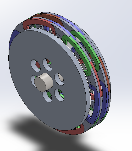
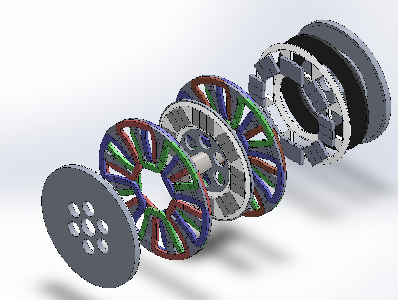
I decided the rotor diameter should be about 200mm, for an air core axial flux PM motor with stator sandwiched by two PM rotors. Doing a simple CAD layout, an 8 pole / 3 phase wave winding seems reasonable. Coils are made to have 50mm^2 cross section. I have 30x15 N42SH magnets available. The Google tells me that for a 50mm^2 cross section of copper, about 100A current sustained seems reasonable.

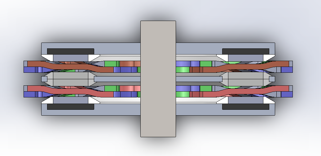
I've made the winding in the relevant segments of the stator to have a rectangular cross section, 5mm deep and 10mm wide (and 30mm long). Total gap between rotors is thus 9mm, with 2mm air gap on each side of the stator. A quick FEMM simulation told me to expect a top field strength of about 0.5T from the magnetism, provided a 5mm steel backing plate . FEMM also tells me that for 100A, about 1.5N of peak force per phase per pole, for a total of 12N per phase, [strike]which translates to 160Nm torque[/strike] (EDIT: the torque was wrong, its only 0.9Nm), assuming the effective/mean radius of the motor is 75mm (200mm outer diameter, 10mm inset for the 30mm magnets, so 150mm mean diameter). The FEMM numbers are also what I got from calculating manually, based on a current carrying wire in a static magnetic field.

This being a wave winding, I have to admit I hadn't had a clue how to compute its inductance. My classes on this subject are long in the past, but if I'm not completely mistaken, assuming its a 150mm diameter ring should approximate it nicely, which puts me at 4uH inductance for a single turn, and about 7mH for 50 turns of wiring. I figured I'd aim for 6000rpm top speed, so I computed a 400Hz self induced EMF of about 35V @ 50T and 0.75V @ 1T, which seem reasonably little that I won't be worrying about this any further.

As a sidenote, at 6000rpm there's considerable load on the rotor, but nothing to worry about at this point.

The more interesting thing is the dynamic EMF from the magnets. For a single turn of 30mm length wire, I get about 0.7V @ 400Hz. For the 8 pole wave winding, this results in 5.6V back EMF on a single turn, or for the 50T version, 35V and 280V respectively. The ohmic resistance of the wiring is 0.24mOhm for 1T, and 600mOhm for 50T.

(EDIT: solved via fixing torque, yay!)[strike]Now, this is the point where I don't see the numbers adding up. 160Nm @ 6000rpm are roughly 100kW mechanical power, but how does this compute electrically? From no electrical property do I see where the 1000V @ 100A for 100kW power are supposed to come from. I'm clearly being a dunce and I'm skipping a step or doing something wrong somewhere, maybe something about the dynamic interaction of the magnetic field / voltage / current?[/strike]

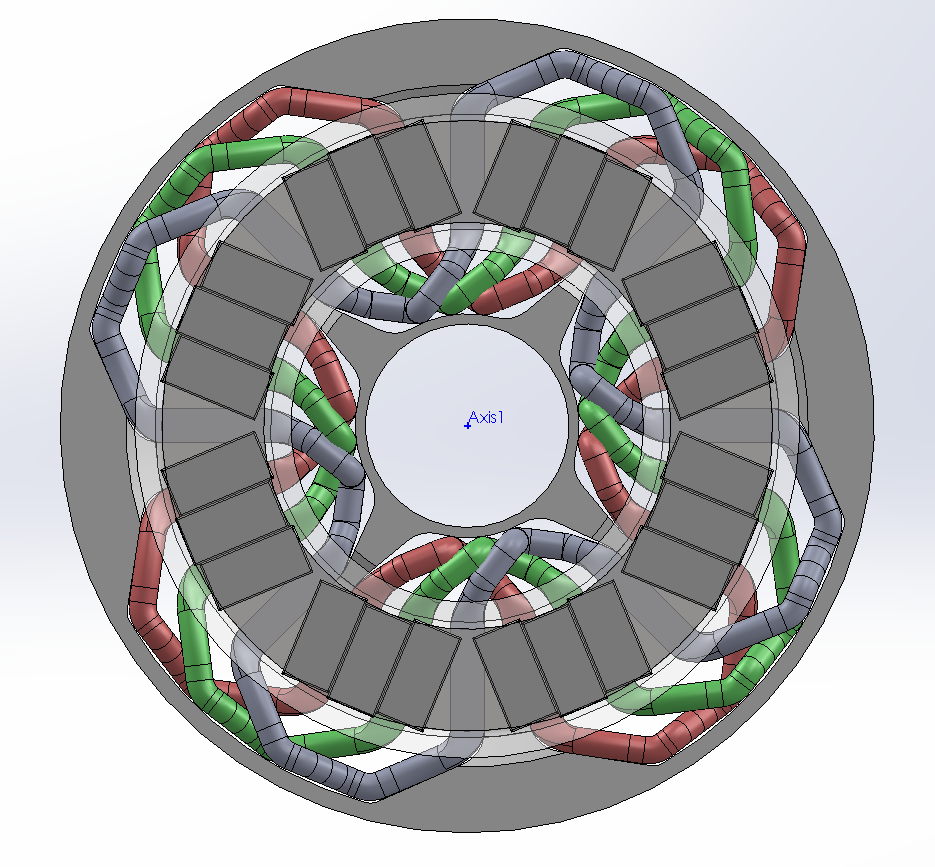
Here's a view with the rotor disc being semi-transparent, magnets, and the stator coils behind:
upshot_YlJq5llC.png
 
This seems like an interesting project and I hope one of the motor experts on this forum will be able to advise you :)

I'm not sure if it will help, but there were two things I didn't follow in your description:

1) The specified 160Nm of torque seems very high for a relatively small diameter motor? You calculate 12N of force per phase, but assuming this is applied entirely tangentially and by all three phases simultaneously, this would surely provide 36N of rotational force at 75mm radius = 36 x 0.075 = 2.7Nm?

2) Does the 50mm^2 refer to the total cross-section of the copper strands used for the windings? If so that sounds considerable: just shy of 0 AWG and rated for around 250A in chassis wiring. I think that would be very conservative compared to peak ratings in a motor.


Good luck!
 
Punx0r said:
This seems like an interesting project and I hope one of the motor experts on this forum will be able to advise you :)

I'm not sure if it will help, but there were two things I didn't follow in your description:

1) The specified 160Nm of torque seems very high for a relatively small diameter motor? You calculate 12N of force per phase, but assuming this is applied entirely tangentially and by all three phases simultaneously, this would surely provide 36N of rotational force at 75mm radius = 36 x 0.075 = 2.7Nm?

2) Does the 50mm^2 refer to the total cross-section of the copper strands used for the windings? If so that sounds considerable: just shy of 0 AWG and rated for around 250A in chassis wiring. I think that would be very conservative compared to peak ratings in a motor.

Good luck!

Duh! Thanks! You're spot on with the torque, I wasn't seeing the forest because of all the trees! If I had paid attention to the units, like was beaten into me in the physics lectures, I might have caught onto this silly mistake! With the corrected torque, The power becomes ~1.1kW mechanically, which DOES match the electrical power based on back EMF (11.5V/100A).

and as for 2) yes, the electrical current was chosen very conservatively, as this just the first iteration of the design, I had no idea what kind of power or torque output to expect. Unfortunately I don't have tools for computing the thermal side of things, I couldn't get to grips with FEMM for that so far.

Now back to the drawing board!
 
So, I made a SAGE worksheet for this, though it seems like you have to login to see it, so here's a text version:

Code:
meanMagneticRadius = 0.075
magneticFieldStrength = 0.5
magnetHeight = 0.03
numPoles = 8
numPhases = 3
windingCrossSection = 50.0e-6
windingCurrentDensity = 4.0e6
targetRPM = 6000
mu0 = 4*pi*1e-7
copperResistivity = 1.68e-8
coilTurns = 20

totalWireLength = coilTurns*(magnetHeight*numPoles + meanMagneticRadius*2*pi)
wireCrossSection = windingCrossSection/coilTurns;
ohmicResistance = copperResistivity*totalWireLength/wireCrossSection
wireCurrent = windingCurrentDensity*wireCrossSection
ohmicLoss = ohmicResistance*wireCurrent^2
ohmicVoltage = ohmicResistance*wireCurrent

poleCurrent = windingCrossSection*windingCurrentDensity
forcePerPole = poleCurrent*magnetHeight*magneticFieldStrength
forcePerPhase = forcePerPole*numPoles
torquePerPhase = forcePerPhase*meanMagneticRadius

mRotationalSpeed = 2*pi*targetRPM/60
eRotationalSpeed = mRotationalSpeed*numPoles/2
emfPerPole = 2*magneticFieldStrength*magnetHeight*meanMagneticRadius*mRotationalSpeed*coilTurns
emfPerPhase = numPoles*emfPerPole

windingRoundDiameter = sqrt(windingCrossSection)
windingMeanRadius = meanMagneticRadius
phaseInductance = mu0*coilTurns^2*((1+((windingRoundDiameter/2)^2)/(8*windingMeanRadius^2))*log(8*windingMeanRadius/(windingRoundDiameter/2)) + ((windingRoundDiameter/2)^2)/(24*windingMeanRadius^2) - 1.75)
phaseInductanceLong = mu0*coilTurns^2*pi*windingMeanRadius^2/windingRoundDiameter

didt = wireCurrent*eRotationalSpeed;
emfPhaseInductance=phaseInductance*didt;

mPower=torquePerPhase*mRotationalSpeed
emfCombined=emfPhaseInductance+emfPerPhase
voltageCombined=ohmicVoltage+emfCombined
torqueMotorConstant = torquePerPhase/wireCurrent;
electricalMotorConstant = targetRPM/emfCombined

outputVars = ['targetRPM','phaseInductance','emfPhaseInductance', 'emfPerPhase', 'emfCombined','ohmicVoltage','voltageCombined','wireCurrent', 'torquePerPhase','forcePerPole','mPower','ohmicLoss', 'ohmicResistance', 'torqueMotorConstant', 'electricalMotorConstant']
outputUnits = ['RPM', 'H', 'V', 'V','V','V','V','A','Nm','N','W','W','Ohm','Nm/A','RPM/V']
outputExpr = [n(globals()[identifier]) for identifier in outputVars]
table(columns=[outputVars, outputExpr, outputUnits])

which outputs:

[pre]  targetRPM 6000.00000000000 RPM
phaseInductance 0.00170178015920447 H
emfPhaseInductance 42.7704003694530 V
emfPerPhase 226.194671058465 V
emfCombined 268.965071427918 V
ohmicVoltage 0.955905078963702 V
voltageCombined 269.920976506882 V
wireCurrent 10.0000000000000 A
torquePerPhase 1.80000000000000 Nm
forcePerPole 3.00000000000000 N
mPower 1130.97335529233 W
ohmicLoss 9.55905078963702 W
ohmicResistance 0.0955905078963702 Ohm
torqueMotorConstant 0.180000000000000 Nm/A
electricalMotorConstant 22.3077292830121 RPM/V[/pre]


I hope the numbers are correct this time :)

In the meantime, I've found a source that claims up to 15A/mm^2 in a winding can work with adequate cooling, which would put this setup at 4kW per phase, so close to 12kW total? According to FEMM, adding two more air core stators, for a total of 3 stators and 4 magnet layers, results in a slightly reduced field strength of 0.45T vs 0.5T originally, which would put me in the 30kW ballpark, right? Not too bad for a motor that would theoretically be a mere 64mm long at a 200mm diameter, if my numbers are correct this time.
 
Hi dognotdog,

Leaving aside the numbers for a moment, I guess the elephant in the room is the eddy current losses.... With solid copper areas of 30mm x 10mm in the magnet path, they'll be not inconsiderable....
 
Miles said:
Leaving aside the numbers for a moment, I guess the elephant in the room is the eddy current losses.... With a solid copper cross-sectional area of 50^2mm in the magnet path, they'll be not inconsiderable....

Yea, if it was solid, but that's just the alotted space, the number of turns in that space would depend on how one would adjust the voltage/current balance, right?

Seems like if I put the numbers in the wikipedia formula, solid copper would result in over 3.5kW of eddy current dissipation for the whole motor, which is considerable indeed, if a single solid copper conductor was used!

EDIT: though from eq. 23 in http://www.jpier.org/PIERB/pierb07/07.08022801.pdf, the total would only be ~320W? Which is the correct way to calculate?
 
It might be worth adding up the total weight of the active materials. If you're getting a continuous torque density of much more than 5Nm/kg, there's likely to be something wrong with your calculations.
 
Miles said:
I'm sorry, I corrected my post as you were replying.

I did still think you were using some kind of solid fill, though..

Heh, editing madness :)

Anyhow, so 320W for all 24 poles sound about right for a solid, if the copper is 30x10x5mm? The Wikipedia infinite sheet approximation is 10x that, quite frankly I haven't a clue what's even the right ballpark for this figure.

And as for the 50mm^2, that's just the cross section of the total winding, so if I used 50 turns, that'd be filled with about 1mm^2 wiring, or so the idea. I can see now how it migh've been confusing. The cross section is kinda fixed because it's a result of the magnetic gap, rotor diameter, and number of poles, and 50mm^2 seems like a good fill ratio for the 200mm outer diameter I am shooting for. Of course, that, too could be changed to get the power output where I want it, if it's not enough to fiddle with the electrical configuration.
 
So, I tinkered a bit more, now looks like:

upshot_a1UT57pE.png

upshot_uPEn5VAx.png

upshot_qACsugxX.png


With these performance numbers for a 200mm rotor:
[pre]  targetRPM 6000.000 RPM
windingCrossSection 50.000 mm^2
coilTurns 10.000 -
phaseInductance 0.425 mH
emfPhaseInductance 30.243 V
emfPerPhase 113.097 V
emfCombined 143.341 V
ohmicVoltagePeak 0.676 V
voltageCombined 144.017 V
wireCurrentRMS 20.000 A
torquePerPhaseRMS 1.800 Nm
forcePerPoleRMS 3.000 N
mPowerPerPhase 1130.973 W
ohmicLossPerPhase 9.559 W
ohmicResistance 23.898 mOhm
torqueMotorConstant 0.540 Nm/A
electricalMotorConstant 41.858 RPM/V
mPower 6785.840 W
mTorque 10.800 Nm[/pre]

The thing weighs in at 8kg as you see in the above pictures, which isn't great, but the current is probably set conservatively, as I find it hard to gauge the thermals at this point. A simulation with convection cooling tells me each stator could dissipate at least 100W with a bit of air cooling, while with the above numbers I'm at 30W ohmic loss per stator, so probably a decent amount of wiggle room there, even if there are unaccounted eddy losses in the conductors.

There are three rotor discs, with the two outer having an iron inlay for flux. It boosts field strength from .35 to .5 T, so certainly worth it. The inner rotor has a double stack of magnets, mostly so that things fit with the extra space needed by the wave winding. I'm not sure if this magnet arrangement is feasible, but 15x30x6 N42SH magnets were the only (suitable) ones I found available easily, so far. Proper pie shapes may be better, but I doubt I can find appropriately sized stock magnets. The 2mm gap between magnets and coil could probably be reduced, going from 2mm to 1mm seems to give a 7% boost in field strength according to FEMM. But 2mm should intuitively be better for airflow.

The thing is basically designed around my shop capabilities, which are limited by the 240mm lathe.
 
Back
Top