Enlighten me please: why focus on P connections, not S?

kevbo

100 mW
Joined
Oct 3, 2011
Messages
38
The images below are lifted from other posts, which I am not linking to because I don't mean to pick on anyone in particular. I just want to
show examples of what I am talking about, as this construction seems pretty typical. I'm sure the batteries in the photo work
just fine as is...but maybe they could be better?

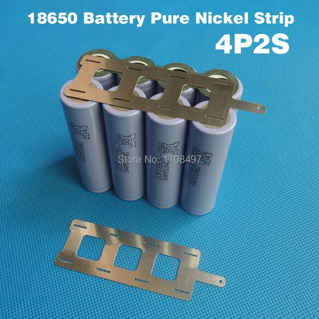
The photo shows the cells connected in parallel bunches, with just two straps carrying the (series) load current.0
view%25204.png


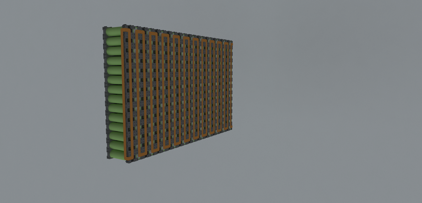
This one shows just one strap carrying load current between parallel sets.
IMG_20150915_152724_zpslsy3y2i4.jpg


If there were, instead, many short straps between just two cells, creating a bunch of series strings, then the resistance of all
the straps would be in parallel, and much lower which might be helpful especially if they are steel or nickle.

The second photo might be hard to do something that with, but the first photo seems to be begging for it.

Of course you'd still need to add a parallel rail down the "ladder rungs" of series straps , but that only carries any inbalance load or charging current, which
will be only a fraction of the load current. Of course you'd still need a good parallel connection at each end of the strings.

It seems to me that the resistance of the battery could be lowered if the designers thought about making series strings first, and paralleling them after, rather than
thinking in terms of making parallel bunches and then putting those in series.

Or am I missing something?
 
kevbo,
Surely you are trying to start an argument (I am smiling). I am a strong proponent of serial blocks that are paralleled. I am also not a proponent of spot welding or permanently fixed cell to cell connections. You can PM me if you want to discuss alternatives. I am not interested in arguing on this forum because it seems many have very fixed views on the subject. EVERYONE is entitled to their opinions and designs. Good luck.
 
Nickel strip has a resistance measured in the double digits milliohms per meter (around 50mOhm depending on width and thickness).

Considering a good single 18650 is around 10mOhm, not designing the pack well could make a measurable impact. But unless you really bork it up, I don't think it will make that much of a difference. The cells will age within a few months and that gain in internal resistance alone with dwarf the extra resistance from poor design.

As the other link Hillhater provided though, you may put uneven wear on your battery. Again though, unless you really bork it up AND drive your packs to within inches of their lives, I doubt it will be really day to day noticeable.
 
Hillhater said:
What you have missed is numerous other threads discussing this same topic.
Like this one..
https://endless-sphere.com/forums/viewtopic.php?f=14&t=84412
and lots of similar ones if you use the search function.

Thanks. Not knowing the name for a thing makes it hard to search for.
 
The points you raise are correct. Notice the width of the series and parallel paths on this common nickel bus plate, they are all the same width and thickness.

Ni-201-1-4H-Pure-Nickel-Strip-4P2S-18650-battery-nickel-strip-2S4P-nickel-belt-0.jpg_640x640.jpg


The parallel connections can be very thin, and very narrow, because they only carry the balancing current, and when all the cells in that P-string are very close to the same voltage, the balancing current is very low. However, in order to make the plate fast and cheap with laser-cutting, the thickness of the entire plate is the same.

The parallel strip widths are also much wider than needed, so, why are they not narrower, to save on nickel, allowing the leftover cuttings to be recycled? The bus plates don't just carry current, they add significantly measurable structural rigidity to the pack.

Nickel is more expensive than copper (or brass), and it has high resistance, bad for cost and performance. So, why do they still use nickel? it spot-welds fast and easy using inexpensive machines. There is a machine that can spot-weld copper busses onto 18650 cells, but it is much more expensive. Copper busses also corrode easily in salty moist air, like on a cargo ship carrying batteries from China to the US.

For low-power battery packs, nickel works OK. Maybe it wastes some watts converted to waste heat. If you look at the batteries from hot rod EVs, the series connections are all thick copper, and they have quite a few strips (bars?). Some even use a wide plate instead of a couple strips.

Tesla uses a thick nickel-plated copper plate.
 
Most 18650 pack busing looks to me like the guy who spot welds it just randomly adds nickel strip bits until eventually it ends up at the intended voltage.
 
spinningmagnets said:
The parallel connections can be very thin, and very narrow, because they only carry the balancing current, and when all the cells in that P-string are very close to the same voltage, the balancing current is very low. However, in order to make the plate fast and cheap with laser-cutting, the thickness of the entire plate is the same.

.
wouldn't it also be carrying the current from the cells? so if it were 10s4p for example and doing 50 amps total there would be 12.5 amps at minimum. If it were the configuration in the top left of the attachment I post here, from bottom cell to top, that'll be 12.5 from bottom cell to second, and then 25 amps from the second to third, and 37.5 going from the 3rd to the fourth. right? In the other configurations of cells shown there are more series connections and the max current in the parallel strip therefore would not build up beyond whatever distance it has to travel across adjacent cells to get to the series connection.
 

Attachments

  • fullsizeoutput_1.jpeg
    fullsizeoutput_1.jpeg
    49.2 KB · Views: 1,794
You're on the right track Hummina, the most ideal is to have strips with your parallel groups, that are also the series connections.

DSCN2391.JPG
 
looks like spot welded copper and ready to be put in orbit. did you use a special welder?

My question as to how much current will flow in the parallel connections, its as spinning magnets says and u can have only tiny current flowing in the parallel connections if done right and when done so it also evenly heats all the cells. The example pic above of the even heating for low power (strangely) would be an example I believe in which there would be very small current flowing in the parallel connections. Obvious...when u know it.
 
There is nothing wrong with thick and wide parallel connections. However, using the common "ladder style" bus plates I posted a pic of...the example in the graphic that is closest to it is the one labeled "not perfect current share". If you move the plus and minus end-parts of the "perfect current share for high power" graphic onto the "not perfect current share"...then you would have what most packs have. The bus plates look like a ladder. If you look at the bus-plate as if its a laddr, the two ladder side posts are the parallel connections and they carry very little current. The rungs of the ladder are the series connections and they carry all the current.

The 0.20mm thick pure Nickel ribbon that is commonly used is absolutely fine for the parallel connections, it is the series connections that carry the high current. If you connected all of the negative ends on the first row with a fat copper wire, and then connected all the positives on the last row with a thick copper wire...you could actually cut all the parallel connections and the battery pack would still work. It would be impossible to balance the cells, but the pack would charge and discharge fine at full rated amps. Balancing is important, I'm not recommending no balance...all I'm saying is...most commercial pack busses are overkill on the parallel, and very weak on the series.

If you got hired as an electrician, and you specced pure nickel wire for a 50A job instead of copper? You'd be fired. If it's a high corrosion environment, maybe you'd get away with nickel-plated copper,...that's what Tesla uses, and I Imagine it's partially because they have no control over where the drivers take their cars...gotta plan for worst-case scenario...

For the OP, the first pic you posted (green cells) has a horrible series path for the max current. there are 14 cells per parallel string, with two cross-over legs on each bus-ribbon, so...best case is 7 copper bars connecting each 2-cell pair in one string to the other...for Doctor Bass's "perfect current share" (which I agree with).
 
Ok the first battery has poor series at high power. But how will it perform at low power but need high capacity. Will it wotk over time or will the end cells be over worked. I quess it depends on the power demands ?
 
spinningmagnets said:
...you could actually cut all the parallel connections and the battery pack would still work. It would be impossible to balance the cells, but the pack would charge and discharge fine at full rated amps. Balancing is important, I'm not recommending no balance...all I'm saying is...most commercial pack busses are overkill on the parallel, and very weak on the series.

).

But you could still balance, just not all the paralleled cells at once which is easier for sure right? Diverging further but related: in ur scenario of running pure series strings with no parallel connections, there wouldn't be any hot spots and would've shown well as an example above, and people say the paralleled cells are a benefit in their self balancing, but wouldn't it be a burden in that once they're paralleled you don't know what's happening with individual cells anymore and one bum cell in there you'd never know which it was bringing the whole discharge energy of the parallel group down as the voltage will drop due to the one bum cell. I'm liking the all series connections
 
Back
Top