
You are using an out of date browser. It may not display this or other websites correctly.
You should upgrade or use an alternative browser.
You should upgrade or use an alternative browser.
EV-1 Conversion
- Thread starter JCG
- Start date
Jay64
100 kW
For some reason that video just totally reminded me of the ending of Ferris Bueller's Day Off. v :lol:
Awesome news to see it running.
Awesome news to see it running.
TylerDurden
100 GW
Pretty damn exciting, IMO...
Excellent work. Kudos and congrats.
Excellent work. Kudos and congrats.
paultrafalgar
10 kW
+1
JCG
100 W
- Joined
- Nov 10, 2008
- Messages
- 174
Jay64 said:For some reason that video just totally reminded me of the ending of Ferris Bueller's Day Off.
Yes - the next step is to run it in reverse for a while and get that odometer back to zero before Dad gets home! :lol: Glad y'all liked the video. What a rush it was to see those wheels move after all this time.
Next job is getting all the wiring moved to the interior and drilling holes & putting grommets in. Running the 4/0 through into the trunk will be a real chore.
In addition, it's time to see if the DC/DC converter still works, then to make a plan on how to get that battery tray raised back up and inside (might be able to borrow the school's lift). Also...
Sounds like you could use some of the scooter motor controllers. They're usually 24V, but if you modify them for the LVC (if they have one) and/or wire around the keyswitch relay, they'd probably work.
For a much more reliable premade solution, the 2QD by http://4QD.co.uk would work, which it shows he has in stock (I used one I modified for CrazyBike2's powerchair motor).
For a much more reliable premade solution, the 2QD by http://4QD.co.uk would work, which it shows he has in stock (I used one I modified for CrazyBike2's powerchair motor).
wrobinson0413
1 kW
.
AndyH
10 kW
JCG said:ADVICE NEEDED! The rear drum brakes are operated by small brushed DC motors (each is 12 V, and about 150 W maximum) that push out the drums. Need a small PWM controller with a potentiometer (or similar) input for them. The idea is to adjust torque to have the drums close with varying force. Any suggestions? Thanks in advance.
Maybe... Check out the MC-1230 DC motor controller. I ordered a kit on the 25th and it arrived today. It's supposed to do 11-15V in and handle up to a 30A load.
[edit] Built the kit last night. It's got a heavy board and lots of copper top and bottom - crank the soldering iron heat up before starting. I don't know yet if it'll control a motor (or two...) but it does work as a light dimmer. :wink:
View attachment controller.jpg
[/edit]
Andy
That sounds like a weird braking system.
If you disconnect power from the brake motor, do the brakes release by themselves or do you need to power it in reverse?
When the brakes are applied and holding steady, does the motor just sit there stalled with full current?
Assuming the braking force is roughly proprotional to the brake motor current, then you would want some kind of current mode controller that increases the motor current as the brake pedal is pushed. You would need some way to adjust or calibrate this I'd think too, so that the brakes don't come on too much or too little.
Does the brake pedal have some kind of pot or encoder?
JCG
100 W
- Joined
- Nov 10, 2008
- Messages
- 174
Hi fetcher,
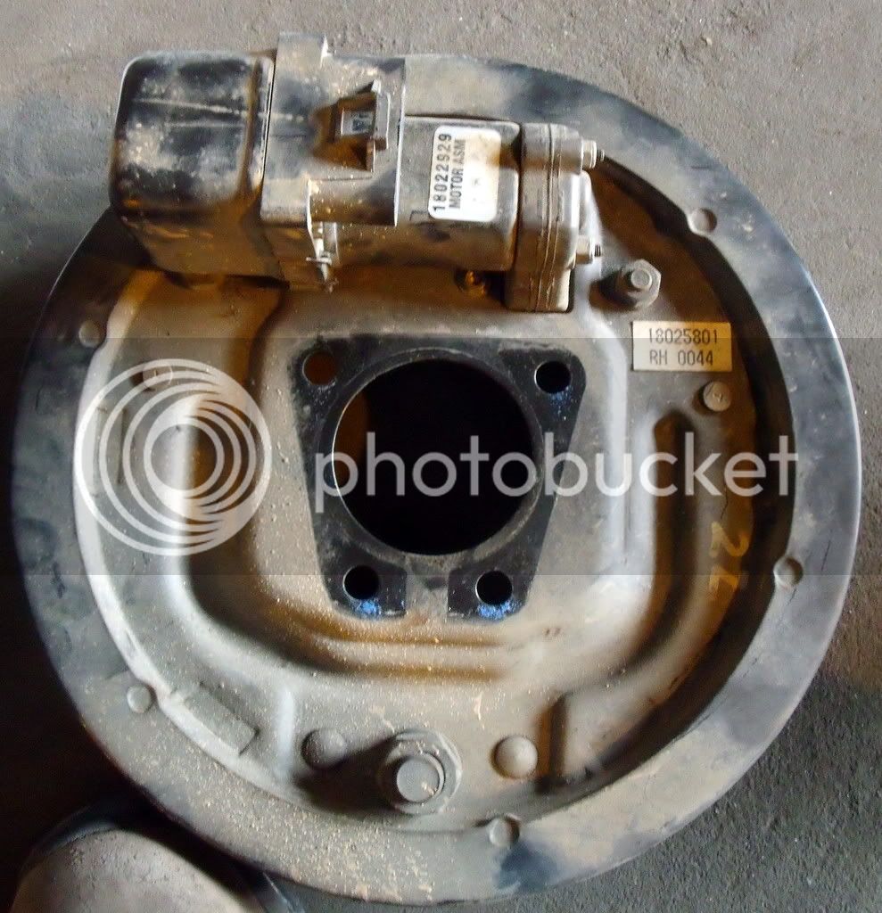
You're right, it's weird. I had to take the assembly apart to see how it worked, but essentially you have a small motor mounted behind the drum backing plate that, through some gears, spins a threaded bolt (with an end cap fitted with a retaining ring) that extends a rod against the inside of one of the brake pad levers. It pushes with more force the more voltage that you give it, and it reverses direction if you switch the polarity.
Rear (motor) side of backing plate:
Front (telescoping rod) side of backing plate:
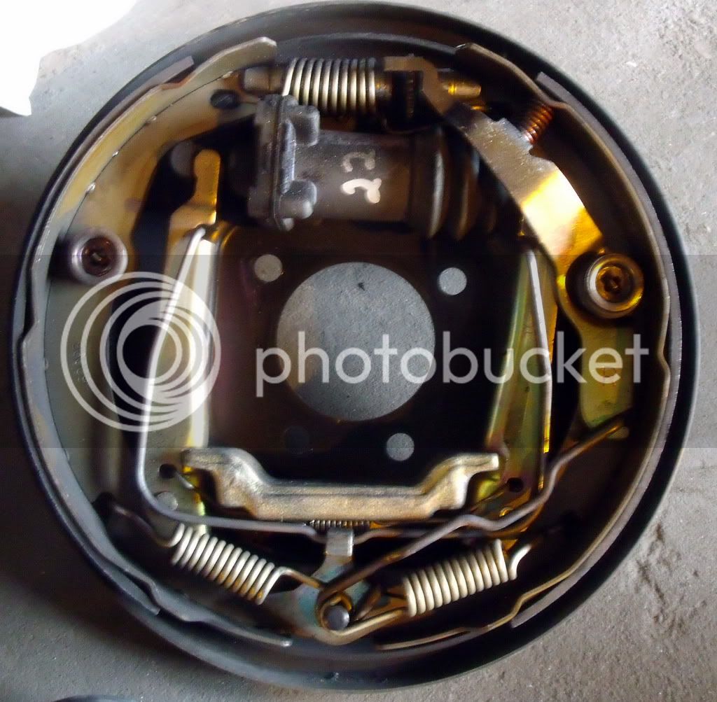
So, if you limit the voltage to limit the motor's torque, it can't open the drum all the way, and so the pad slows the wheel down more slowly. I found that by applying a different voltage (between about 2 to 12 volts), and allowing the motor to draw as much current as it wanted to, the braking force could be adjusted. My first test was screwed up because I was inadvertently limiting the current along with the voltage.
The brake reverts to the closed position when power is removed from the motor, and I believe this is because the threading on the bolt is angled sufficiently steeply so that the springs can push back against it (now unopposed by motor torque) and thereby reduce the rod to its original length.
The old modular interface between the brake pedal and the brakes themselves is long gone, GM removed it before vehicle donation. But, using a lever-based pot hooked to the brake pedal and a brushed controller with PWM to cut down on the voltage should do the trick, at least I hope so!
You're right, it's weird. I had to take the assembly apart to see how it worked, but essentially you have a small motor mounted behind the drum backing plate that, through some gears, spins a threaded bolt (with an end cap fitted with a retaining ring) that extends a rod against the inside of one of the brake pad levers. It pushes with more force the more voltage that you give it, and it reverses direction if you switch the polarity.
Rear (motor) side of backing plate:
Front (telescoping rod) side of backing plate:
So, if you limit the voltage to limit the motor's torque, it can't open the drum all the way, and so the pad slows the wheel down more slowly. I found that by applying a different voltage (between about 2 to 12 volts), and allowing the motor to draw as much current as it wanted to, the braking force could be adjusted. My first test was screwed up because I was inadvertently limiting the current along with the voltage.
The brake reverts to the closed position when power is removed from the motor, and I believe this is because the threading on the bolt is angled sufficiently steeply so that the springs can push back against it (now unopposed by motor torque) and thereby reduce the rod to its original length.
The old modular interface between the brake pedal and the brakes themselves is long gone, GM removed it before vehicle donation. But, using a lever-based pot hooked to the brake pedal and a brushed controller with PWM to cut down on the voltage should do the trick, at least I hope so!
Interesting. It sounds like it could be tricky to make it work safely.
Are the front brakes hydraulic? Maybe there is a pressure sensor on the hydraulic line that is used to control the voltage to the rear brake. That would seem better than going by pedal position.
Are the front brakes hydraulic? Maybe there is a pressure sensor on the hydraulic line that is used to control the voltage to the rear brake. That would seem better than going by pedal position.
AndyH
10 kW
fechter said:Interesting. It sounds like it could be tricky to make it work safely.
Are the front brakes hydraulic? Maybe there is a pressure sensor on the hydraulic line that is used to control the voltage to the rear brake. That would seem better than going by pedal position.
Like some type of proportioning valve equivalent?
Cool brake system! The front side looks like a standard drum brake though the 'wheel cylinder' is different. I guess I would need someone to tell me again how the electric actuator is lighter than a hydraulic line...
VW and Audi cars have had electric parking brakes for a couple of years. A tech needs a scan tool to tell the brake controller to relax the rear brakes so they can change the brake pads. It does allow them to do things like 'auto brake' to stay on a hill. It takes the fun out of coordinating gas, brake, and clutch at those up-hill stop lights, though. :wink:
paultrafalgar
10 kW
If I were doing this I would not want to rely solely on electric/electronic control of the braking system. Any error could lead you into an accelerating Prius nightmare. At least make the Parking brake strong enough to stop the car in an emergency and make it mechanical (possibly hydraulic?).
bigmoose
1 MW
This might be as simple as getting an old "electric trailer brake controller" typically used with a SUV or pickup to tow a large trailer with electric brakes. The one I used years ago was from Kelsey Hayes. It spliced into the rear hydraulic system and was simply a power resistor that changed resistance from infinite (brakes off) to full on. The controller had a knob that I would play with to change sensitivity. Basically changed the delta resistance/delta pressure. This would give you the ability to tune the proportionality factor of your rear brakes.
Basically if you are changing voltage on the motor, and allowing "saturation" current to flow; you are basically controlling motor torque as you said. That can be done with 12V and a simple PWM approach to the motor. If you roll your own PWM controller, a simple algorithm based on sensing front hydraulic pressure with a transducer should work with a transfer function PWM% = Constant *Pressure_front/Pmax_front
The new electric trailer brake controllers may be PWM based using an accelerometer. I would not use these as unpredictable results could occur because of the accelerometer. The old style that sensed the hydraulic pressure may be more useful and more safe.
Best of luck on your conversion! The more I read about the EV-1's the more I am impressed with the design. GM appears to have had a home run winner 15 years ago. Why they don't resurrect it with lithium I do not know...
JCG
100 W
- Joined
- Nov 10, 2008
- Messages
- 174
Fetcher & Paul - yeah, the front brakes were designed as "electric-hydraulic," meaning that you could push on the brake pedal and get some pressure to close the front calipers, but there was also an electrical signal sent to the piston to boost the pressure (presumably the same signal sent to the rear brakes). So, with no electricity, you have what I'll term "weak" braking at the front wheel only.
Dave - the trailer brake controller I received a while back doesn't use PWM unfortunately. It seems to be a current limiter (always at 12 V though) to make the trailer brake's electromagnet stick with more or less force.
There's a cheap, programmable 12 V brushed DC controller on the way, it should be here by early next week (tomorrow if I'm lucky). I think I've got all I need to test it out quickly once it arrives. I'll have a pedal pot to use for an input, but I'll try to find out if there's something built into the brake pedal (in terms of position sensing) that I could use instead.
In the meantime, I'm still working with the placement of wiring and control items inside of the car. Soon, I'll need to see if I can borrow the school's lift for an afternoon and get the capacitor tray bolted in again. Hopefully there will be a volunteer or two around that day to help out. Some good news is that the DC/DC converter that originally came with the car works - feeding off the high voltage bus in the controller. One less thing to do!
JCG
100 W
- Joined
- Nov 10, 2008
- Messages
- 174
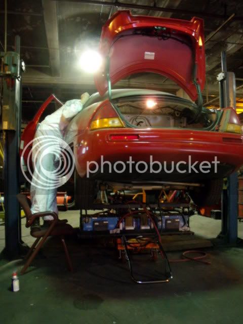
Big update time!
Today was the day to get the capacitor bank installed, and everything all buttoned up. The control panel and all the other bells and whistles (DC/DC converter, high voltage monitor wires, coolant for motor/controller, power steering fluid, windshield wiper fluid, etc.) we all taken care of. One thing I had to do in order to make sure the coolant system was leak-free was to remove the inductive charging unit:
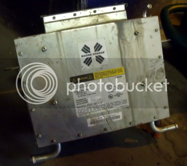
It was just extra weight anyway, and came off pretty easily. I had convinced the folks who run the university's garage that I needed to use the lift, and this morning Eric Cardwell (we met at a meeting for EVA/DC where I gave a presentation about the EV-1 conversion project last winter) came by and we got things rolling. Once the car was pushed to the lift area, we loaded the capacitor tray onto a lift table and wheeled it over there. This little table ended up being quite handy.
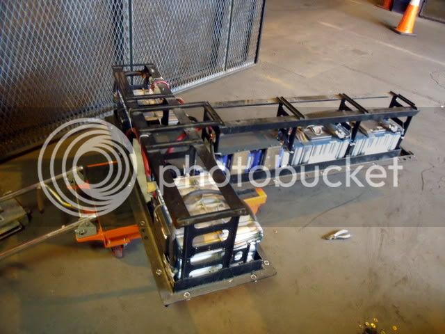
Eric worked the heavy (4/0) cable, which will be run to the generator, up from the tray and back into the trunk via a couple of holes punched in the frame. The second image below shows the lift table being used to line up the tray with the car's cavity.
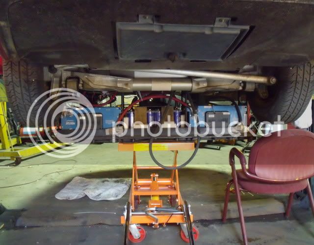
We eventually got it into place and we worked pretty hard for over an hour getting everything mostly aligned. We re-installed the bolts into the tray and secured it into place. The air shields still need to go on, but that can wait.
Eric won the "who can make the floor cleaner by picking up all the dirt on your clothes" contest.

All that work deserved a reward, so we had to charge it up and take a test drive. The charging area is now the trunk.
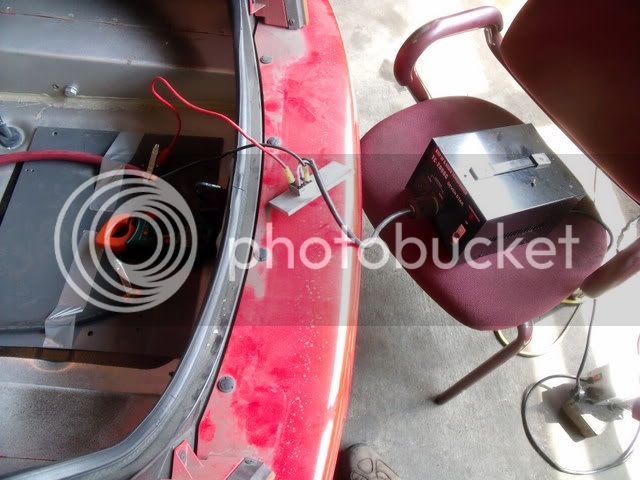

Driving was quiet and smooth - what an experience! We ran about 8 laps around the garage before parking and discharging the caps the rest of the way.
[youtube]aWOvSTCuzus[/youtube]
Today was the day to get the capacitor bank installed, and everything all buttoned up. The control panel and all the other bells and whistles (DC/DC converter, high voltage monitor wires, coolant for motor/controller, power steering fluid, windshield wiper fluid, etc.) we all taken care of. One thing I had to do in order to make sure the coolant system was leak-free was to remove the inductive charging unit:
It was just extra weight anyway, and came off pretty easily. I had convinced the folks who run the university's garage that I needed to use the lift, and this morning Eric Cardwell (we met at a meeting for EVA/DC where I gave a presentation about the EV-1 conversion project last winter) came by and we got things rolling. Once the car was pushed to the lift area, we loaded the capacitor tray onto a lift table and wheeled it over there. This little table ended up being quite handy.
Eric worked the heavy (4/0) cable, which will be run to the generator, up from the tray and back into the trunk via a couple of holes punched in the frame. The second image below shows the lift table being used to line up the tray with the car's cavity.
We eventually got it into place and we worked pretty hard for over an hour getting everything mostly aligned. We re-installed the bolts into the tray and secured it into place. The air shields still need to go on, but that can wait.
Eric won the "who can make the floor cleaner by picking up all the dirt on your clothes" contest.
All that work deserved a reward, so we had to charge it up and take a test drive. The charging area is now the trunk.
Driving was quiet and smooth - what an experience! We ran about 8 laps around the garage before parking and discharging the caps the rest of the way.
[youtube]aWOvSTCuzus[/youtube]
GCinDC
100 MW
AWESOME!!! Congratulations!!! Historic, I'd say...


GCinDC
100 MW
NICE! But I wasn't going to say anything about the decades of dust in the vid... :lol:
See you tomorrow!
See you tomorrow!
GCinDC
100 MW
I DROVE THE EV-1!! It's awesome. I'm speechless.
Just inside the garage for a couple laps, but wow, I was very surprised by the power! Awesome regen! Very effective and very smooth at higher speeds.
No time to write much up now, but I LOVE THIS PROJECT!! I'm kicking myself for not making a documentary of it... The ironies of it all. In a dusty garage at Howard U, a vehicle is reborn...
On one lap, a lady who might have worked there remarked in a drawl, "Oh, you got that little car running..."
If she only knew!
AndyH
10 kW
More genset info. 500CC motorcycle engine, ~20KW genset. Enough to 'range extend' a Toyota RAV4 EV at highway speeds.
The pictures
The document
Alternate Link
http://www.hawkins.info/files/rxt-g_acp_white_paper_range_extending_trailers.pdf
Enjoy!
Andy
The pictures
The document
Alternate Link
http://www.hawkins.info/files/rxt-g_acp_white_paper_range_extending_trailers.pdf
Enjoy!
Andy
JCG
100 W
- Joined
- Nov 10, 2008
- Messages
- 174
AndyH said:More genset info. 500CC motorcycle engine, ~20KW genset. Enough to 'range extend' a Toyota RAV4 EV at highway speeds.
Thanks Andy - I had seen those pictures before but not the whitepaper/writeup. That's going to be handy! It looks like the required power levels I had calculated are similar to those that the AC Propulsion people had. Always good to have a check.
Ypedal
100 TW
oh wow man !!.. this is AWSOME.. ( guys at work just don't understand my freaking out at this !! lol.. ) well done ! 8)
Similar threads
- Replies
- 33
- Views
- 2,735
- Replies
- 12
- Views
- 734
- Replies
- 17
- Views
- 4,429