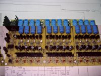
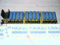
Even Newer 4 to 24-cell Battery Management System (BMS)

reagle said:
Another question- when using your BMS with Thundersky batteries, am I correct to assume that one would need to tweak the voltage limits on both charge and discharge?
Their curves seem to show 2.5v or so ideal LV cutoff, and a charge up to 4.2V , which is kinda strange for LiFePO4. I am contemplating getting a charger/cells package from Elitepowersolutions, but the difference in voltages for their cells vs the PSI/BI/Headway round ones worries me a bit

I don't think they really need to go up to 4.2v. That is quite high.
PJD has been using our BMS with Thundersky cells and it seems to work well. You might get more details from him.
 
After talking to Jennifer from ElitePower, I can now confirm that you are right - the numbers are more of abs max values as opposed to recommended value:
"Our TSL series charger charges the cells to 3.6V per cell, then add 0.6V for the whole pack during the last pulsed charging step. The battery is safe to operate between 2.5V to 4.25V, but we recommend to stay away from the limits. Our charger will take care of over-charging issue, and you need to set maybe around 2.8V cutoff for the motor to prevent over-discharge."

fechter said:
reagle said:
Another question- when using your BMS with Thundersky batteries, am I correct to assume that one would need to tweak the voltage limits on both charge and discharge?
Their curves seem to show 2.5v or so ideal LV cutoff, and a charge up to 4.2V , which is kinda strange for LiFePO4. I am contemplating getting a charger/cells package from Elitepowersolutions, but the difference in voltages for their cells vs the PSI/BI/Headway round ones worries me a bit

I don't think they really need to go up to 4.2v. That is quite high.
PJD has been using our BMS with Thundersky cells and it seems to work well. You might get more details from him.
 
Guys, I have a TS charger from Elite. I use it on A123, TS and LiMn cells with no problems. Yes, you don't get the full energy density of as if you charged higher. This is good and gentle to the cells! And the charger is rock solid in operation. By limiting the charge voltage the cells tend to "self-balance". This is why Elite does not make you have a BMS for a scooter, bike or motorcycle pack of cells. I can confirm that the TS stay nice and balanced with no issues and I am using it in a small car! My charger does 58.2 volts @15amps (current is "alleged" at this time but gets the job done).
Jeff K.
 
At risk of drifting off-topic, I found little self-balancing effect with my Thundersky pack even when charging at just C/5 (8 amp). I'm not sure how far apart the voltages would get, because I'd always interrupt charging while watching the voltages like a souffle in the oven. But at the 59.5 volt cutoff, low cells would be be 3.5's and high cells would have probably reached 3.95 - 4.0 volts per cell. I consider a BMS like Gary and Richards to be mandatory (there, back on topic!).

As far as a 2.8 volt cutoff, the problem is, in cold temperatures (around freezing of a bit below) even a fully charged pack will sag to or below 2.8 volts per cell under what should be a perfectly allowable 2.25C discharge rate. Maybe wishful thinking is setting in with the winter temperatures, but I am skeptical that the 2.5 volt absolute limit applies under the high end of the allowable discharge rate and low temperatures. No other battery works like that. For example for sealed lead acid batteries, going down to 10 volts at 2C causes no harm, but go down to 10 volts at C/20 and the battery would be ruined.
 
PJD, Yes, I agree a bms is good to have. I use Richard/Gary model as well. I forgot to mention that under heavy loads (car 300A plus) they will get out of whack I suppose...
Jeff K.
 
jeffkay said:
PJD, Yes, I agree a bms is good to have. I use Richard/Gary model as well. I forgot to mention that under heavy loads (car 300A plus) they will get out of whack I suppose...
Jeff K.
A BMS is mandatory if you value your expensive batteries. Or at least a per-cell low voltage cutoff (LVC). LiFePO4 batteries are very robust, but low voltage is their achilles heal. And an LVC circuit usually costs a lot less than a battery pack.

rf
 
Gary,

On your website, you show balancers with connectors and/or harnesses to connect to battery packs. What connector type are you using, and is there a convention for pinout?

I'm assembling one of your BMS's and thought if it might make sense to stick to any standard or convention.

Thanks,

Nick
 
for the BMS I built, I found a quick and available solution on connectors for the cell wires, I am using male and female 25 pin D parallel port/printer connectors with solderpot type terminals for the wire end. The contacts can do a bunch of amps at 200 volts or more, so I figure they are fine for the balancing leads.
I also potted where the wires come out of the D connectors with hot melt glue so nothing moves or shorts.

Radio Shack sells them for a couple of bucks.

Its sort of a temporary solution until i get something better. The pins on the male connector could get bent and hit other pins when unplugged, so its not the best connector.
I do have to tape the isolated metal shell of the connectors because its so easy for it to hit battery terminals or electronics and short out.
I had to double and triple check wires and connections with an ohm meter to make sure no shorts and everything matched up before potting it with the hot glue. It still made me nervous to hook them together for the first time.
 
I do have to tape the isolated metal shell of the connectors because its so easy for it to hit battery terminals or electronics and short out.
Cover those terminals. Was looking at a friend's ecar conversion recently, with bare battery posts showing here and there.

An accident waiting to happen!

rf
 
I welded my finger with a 100V Lipo pack the other day.
Even a tiny 26gauge wire can dump a lot of energy before it blows open. . . Certainly enough to melt fingernails :roll:

They sell protective plastic caps for 25 pin D connectors btw.
Another option (and my favorite) is to do as follows:

* Procure a mating connector
* build a tape dam around the back
* pot it with epoxy

Now you have a perfect (non) "shorting plug" that easily comes on and off and protects your contacts.
This is what I do when I want something that is convenient to pull on and off. You can even get tricky and put resistors/active circuitry inside the potting to do other slick things.

-methods
 
This is my first time building a board of any description and I thought I was doing OK, but I've run into a problem and I'm not sure what to try next.

The LVC portion of the boards tests out fine according to Gary's instructions, with each channel tripping at around 2.1V.

When I came to test the charger section I found that the main LED came on red, but none of the channel LEDs would come on. I've tried it with two different 36V chargers, raising the voltage gradually to 50V, which should have been high enough for 12 channels.
This is where I have to own up and admit that having read about someone else here managing to install all the orange LEDs the wrong way round, I found that I'd gone and done the same thing :oops: Maybe I should stick to bashing bits of metal...

Anyway, I replaced them and repeated the tests, but still no life from the orange LEDs. Could I have damaged something else by testing with the LEDs reversed? I've checked and everything seems to be in the right place and the right way round now, but just in case I've screwed anything else up I've attached a photo of the board.
 

Attachments

  • IMG_1212.jpg
    IMG_1212.jpg
    153.6 KB · Views: 3,160
Looks good.

It is possible you toasted something, but the design is fairly fault tolerant.

Can you measure current when you are applying voltage?

Do the resistors get warm?

It sounds possibly like the FET is not going on.

Also if any cell circuit is open, it breaks the series chain. You could try feeding the first 5 cells with 20v or so and see what happens.

Next test I would suggest is to apply voltage and try shorting the output pins on one of the optocouplers and see if you can get the main LED to go green. This tests part of the control circuit. Use a small screwdriver or something and touch the two pins in the corner (see below).
Board test 1.jpg
 
Thank you Richard

I found a tiny solder bridge between R103 (100 ohm) and R104 (the shunt resistor) on channel 6. I hadn't realised how much my near vision had deteriorated until I started doing this. I'm currently shuttling between three pairs of glasses :shock:

Anyway, I repaired that and now all the LEDs light up except on channel 7. The main LED turns greenish as I increase the voltage. The main LED turns completely green and all the orange LEDs go out when I short any of the opto outputs, including channel 7. I've double-checked the LED on channel 7 and it's fine. Any suggestions as to which component is most likely to be at fault?
 
Sounds like you're making progress.

Test R103 and R105 with an ohmmeter.

Sounds like Q101 or R105 is the most likely suspect.

Can you tell if the resistor is getting hot when the other channels are lit up?

If you have a variable power supply, you can test individual channels by clipping onto the legs on adjacent power resistors. Don't feed a single channel more than 5v. If it's working, you can increase the voltage slowly and the LED should come on right at 3.67v or so.
 
Malcolm said:
This is my first time building a board of any description and I thought I was doing OK, but I've run into a problem and I'm not sure what to try next.

The LVC portion of the boards tests out fine according to Gary's instructions, with each channel tripping at around 2.1V.

When I came to test the charger section I found that the main LED came on red, but none of the channel LEDs would come on. I've tried it with two different 36V chargers, raising the voltage gradually to 50V, which should have been high enough for 12 channels.
This is where I have to own up and admit that having read about someone else here managing to install all the orange LEDs the wrong way round, I found that I'd gone and done the same thing :oops: Maybe I should stick to bashing bits of metal...

Anyway, I replaced them and repeated the tests, but still no life from the orange LEDs. Could I have damaged something else by testing with the LEDs reversed? I've checked and everything seems to be in the right place and the right way round now, but just in case I've screwed anything else up I've attached a photo of the board.

Nice work and thanks for the great pic as it will help me with the rest of my build. I had to do this under a big magnifying glass as my eyes are not the greatest with the four feet and under stuff. Have spent a couple hours here and there on the project about four hours into just getting all the resistors on. Looks like another six or eight hours will be needed to finish it.
 
Confusing...

Rx03 and Rx05 are both 100 ohms, as they should be.

Diode check on Qx01 in all permutations gives same readings for channel 7 as for other channels. Same for Ux02.

Using a variable power supply on each channel in turn, each LED starts coming on at 4.25V (?), except for channel 7, which doesn't come on at all, but the shunt resistor does get hot.

Right now it looks like I made a consistent mistake on 11 channels and screwed up no. 7 completely :roll: I've checked resistor positions but they all appear correct.
 
One way I have found to find bad channels is to use an ohm meter and measure from one power resistor to the next where the cell wires come in. (one cell wire to the next cell wire, with it unplugged from the pack)
I'm getting about 250Kohms between each consecutive channel. I'm not totally sure about this value though cause I'm still trouble shooting my board.
I had a couple of fried channels where a loose cell wire hit a terminal on my pack and fried some parts and this told me which channels to replace the semiconductors in. I'm glad i ordered extra parts.
 
If the shunt resistor is getting warm but the LED still does not light up, then it would indicate that perhaps the LED is bad.

Try to measure the voltage across the LED. The LED should light up above around 2v.

The voltage measurements will look whacky with no cells attached. If you dial up the voltage so that the LEDs are just barely lit, then the voltage measurements across the cells should look closer to reality.
 
Looks like my old FalconEV cells. Had to get an extra from Ypedal since I had one going bad. These are not very vibration resistant.

Anyway, charging the one cell with a spare board from my old Flintstone charger.

DK
 

Attachments

  • IMG_2206.JPG
    307.1 KB · Views: 3,077
fechter said:
Try to measure the voltage across the LED. The LED should light up above around 2v.

The LED was fine, but there was a break in the track next to the LED on top of the board (my fault). Fixed that and now all the LEDs light up :D
Thanks again Richard. I must owe you a crate of beer - or whatever your poison is - by now
I'm impressed by how tolerant this board is. If it can survive my cackhandedness it should be very reliable. I feel a lot more confident about building up the next two boards, now I've done one.

Sorry to take up so much space here, but I figure there must be quite a few other people who are building up boards for the first time, who might find my mistakes useful.
 
Malcolm said:
Sorry to take up so much space here, but I figure there must be quite a few other people who are building up boards for the first time, who might find my mistakes useful.

No problem.

I'm slowly working on a testing/troubleshooting guide which I hope will cover most common problems. Ultimately we hope to make fully built and tested boards.

Getting those orange LEDs in the right way seems to be one of the hardest points. It is very difficult to see the flat on the side. We can fix the instructions to point out which hole the longer lead goes to, since this is much easier to see.

Another good trick is to hold the board up to a light and look through it to search for bridged/broken traces. They are much more visible this way.

I designed things to be as fault tolerant as possible. Most single component failures won't take out any other parts.
 
I have a question regarding the troubleshooting of the board.
In the instructions it says that when you hook it up to the charger with no cells connected, you should get a Green main light and all the shunt lights should be on.
When i do this with mine I get a split second flash of all the shunt LED's and a Green main LED. The shunt LEDs stay off. Is this proper operation?
 
Yes, that would be proper operation if the applied voltage is enough to turn on all the shunts and it goes into auto-shutdown.

For a more entertaining display, try using a jumper to jump two adjacent power resistors (the side toward the battery wires) above cell #5. This will prevent one shunt from coming on and all the other cell LEDs should light up. Move the jumper over one cell to test the one that was jumpered.
 
Hey all

just wanted to ask if there is a 10 cell version of the same board instead of having to purchase the 4-24 cell board for my a123's and separating the boards.

thanks

steveo
 
Back
Top