Even Newer 4 to 24-cell Battery Management System (BMS)

Nice drawing.

OK on the test. Put the capacitor back.
For some reason the drive for opto #3 is too low.
Measure the resistance (power off) across R106 on all channels and verify they look like 820 ohms.
Verify continuity between pin 2 on the opto to R106 on each channel. Verify continuity between the other side of R106 to the negative bus (one side of the power resistor).

Power on and measure from pin 1 of each opto to the outside of the power resistor on the corresponding channel.
 
Measure the resistance (power off) across R106 on all channels and verify they look like 820 ohms.
all are at 820 ohms
Verify continuity between pin 2 on the opto to R106 on each channel. Verify continuity between the other side of R106 to the negative bus
continuity is there
????
 
fechter said:
Power on and measure from pin 1 of each opto to the outside of the power resistor on the corresponding channel.

Try the voltage measurement. It's the voltage across the opto emitter and the 820 ohm resistor combined.

I'm still puzzled about what could be causing your problem. On the positive side, most of it is working properly.
 
Thanks to fechter to be so patient !
I have some new measurements done- main voltage 16V/0,45A all leds lit:
Curious are the voltages at #3 with and without the resistor (820 ohms) the same voltages???!!! So I replaced this resistor(was ok.) but the new one did the same!
 

Attachments

  • BMS2_2_4_2.jpg
    94.5 KB · Views: 2,520
from 820 ohm resistor to pin 1 of the optos:
circuit #1: 1,72V
circuit #2: 1,28V
circuit #3: 0,64V
circuit #4: 1,25V
 
ggoodrum and fechter a suggestion:

when you release a new board design it would be nice if you could also post the art file that is sent to the board etcher company for production so we users who have access to a board etcher service company or can etch it ourself using the radio shack etching kit.

or recommend a prototyping program that can take a schematic and convert it to the art file.
 
manfred59 said:
from 820 ohm resistor to pin 1 of the optos:
circuit #1: 1,72V
circuit #1: 1,28V
circuit #1: 0,64V
circuit #1: 1,25V

That is most bizzare. If you didn't live so far away, I'd just have you ship it to me.

Double check the resistance of the R105 on channel 3 and verify 100 ohms.

Verify continuity from the collector of Q101 to the anode of the LED on channel 3.

At this point, it almost boils down to the LED itself, which lights up but appears to be limiting the current or something. You could try and measure the voltage across the LED when it is lit. It's supposed to be around 2v. I've never seen a LED go bad but still light up, but this could be a first. Try replacing the LED perhaps. It is much more likely there is a cold solder joint or cracked trace between Q101 and the LED or from the LED to pin 1 on the opto.

The voltages should be roughly like this when the shunts are on.
 
ejonesss said:
or recommend a prototyping program that can take a schematic and convert it to the art file.

We use ExpressPCB. program is free.
There is a limit to how much information we want to post to protect our intellectual property. The schematic is out there so people can troubleshoot and understand how the thing works. We will not post the souce files for the layout.
 
and thanks for the program recommendations i will look at it and see if i can design my own board .

fechter said:
ejonesss said:
or recommend a prototyping program that can take a schematic and convert it to the art file.

We use ExpressPCB. program is free.
There is a limit to how much information we want to post to protect our intellectual property. The schematic is out there so people can troubleshoot and understand how the thing works. We will not post the souce files for the layout.
 
i was wondering once the leds turn green if the power to the channel is left on will that hurt the cell?

because for those who have left over segments broken off from the board (like me) would like to use them on another project and since the controller is only on the first segment and is used with the bms there is no way to turn off the charging power.
 
ejonesss said:
i was wondering once the leds turn green if the power to the channel is left on will that hurt the cell?
because for those who have left over segments broken off from the board (like me) would like to use them on another project and since the controller is only on the first segment and is used with the bms there is no way to turn off the charging power.

I'm not sure I understand your question.

If you populate the cutoff sections with parts, they could be used as a LVC and the shunts would still work. There would just be no charge control. If your charging source was limited to less than the shunt current, then none of the shunts could ever overvolt and your cells would be safe.

If the charger voltage was set to exactly the voltage where the shunts are just barely starting to turn on, the shunts would be mostly off at end of charge and not get too hot.
If you did this, and your cells were reasonably well matched, you could probably get away with a somewhat higher charge current during bulk charge.

As far as leaving the charger on for long periods, I'm not really sure about that. With a CV at end of charge, the charge current would taper off to near zero. I'm sure it won't hurt the cells to go for a day or so like that. I wouldn't recommend leaving it on charge 24/7.
 
i wanted to make a charger/lvc bms to be able to charge single cells from the 5 volt output of a computer power supply since the 5 volt output can supply a dozen or 2 amps easily.

witch is also the reason i wanted to get the program because i am taking 1 channel from the schematic and drawing up a new layout so that users who want to charge single cells could do so without having to waste the other channels.

maybe i will try to draw up a layout for the charger control circuit so that maybe users would not have to order an entire bms board just for the charging controller.


fechter said:
ejonesss said:
i was wondering once the leds turn green if the power to the channel is left on will that hurt the cell?
because for those who have left over segments broken off from the board (like me) would like to use them on another project and since the controller is only on the first segment and is used with the bms there is no way to turn off the charging power.

I'm not sure I understand your question.

If you populate the cutoff sections with parts, they could be used as a LVC and the shunts would still work. There would just be no charge control. If your charging source was limited to less than the shunt current, then none of the shunts could ever overvolt and your cells would be safe.

If the charger voltage was set to exactly the voltage where the shunts are just barely starting to turn on, the shunts would be mostly off at end of charge and not get too hot.
If you did this, and your cells were reasonably well matched, you could probably get away with a somewhat higher charge current during bulk charge.

As far as leaving the charger on for long periods, I'm not really sure about that. With a CV at end of charge, the charge current would taper off to near zero. I'm sure it won't hurt the cells to go for a day or so like that. I wouldn't recommend leaving it on charge 24/7.
 
The new v2.3 boards will arrive this Friday. It took a bit longer to manufacture them, due to the quantity I ordered. I need to update the BOM files, and the instructions, which I will do in the next couple days. I will also re-enable them on my website, either tomorrow, or Thursday. No need for any "pre-order" requests, as I got sufficient quantities this time to last awhile.

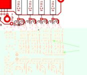
24-Cell%20LiFePO4%20BMS-v2.3-PCB.jpg


There are really only two changes in this version, the addition of a few parts to the 12V regulator section that will allow for much higher pack voltages (100V+...), and the enlargement of the shunt transistor holes to allow the use of the BD136 part, in place of the KSA931, so that when coupled with the use of 3.2 ohm/5W shunt resistors (in place of the 6.8/5W version...), the shunts can handle up to an amp of bypass current, with no problem. The KSA931/6.8 ohm combo can still be used, if 1/2A is enough, which I feel it is for most ebike applications. The 1A accomodation is really for the larger packs being used on scooters and motorcycle conversions.

I also removed the "Test LVC" pads in this version. The problem is that if this is used with the complementary output version of the TC54, it can actually fry the part. It turns out neither Digikey or Mouser normally stocks the TC54VN-210, only the TC54VC-210 version, which has the complementary-type output. Either part works fine with the actual LVC function, but only the "N" version can be used with the "Test LVC" pads. Anyway, that's why I removed it.

-- Gary
 
how do we test the lvc then?

if the concern was frying the tc54 couldn't shorting opto to ground at the minus side of the opto by placing a resistor between ground and the minus side of the opto's led?

the tc54 would not have it's output shorted and yet the current to the led side of the opto would limited enough to not fry them either.


while it is too late now to make the change if it will work it can be something to think about in a future board.


GGoodrum said:
The new v2.3 boards will arrive this Friday. It took a bit longer to manufacture them, due to the quantity I ordered. I need to update the BOM files, and the instructions, which I will do in the next couple days. I will also re-enable them on my website, either tomorrow, or Thursday. No need for any "pre-order" requests, as I got sufficient quantities this time to last awhile.

24-Cell%20LiFePO4%20BMS-v2.3-PCB.jpg


There are really only two changes in this version, the addition of a few parts to the 12V regulator section that will allow for much higher pack voltages (100V+...), and the enlargement of the shunt transistor holes to allow the use of the BD136 part, in place of the KSA931, so that when coupled with the use of 3.2 ohm/5W shunt resistors (in place of the 6.8/5W version...), the shunts can handle up to an amp of bypass current, with no problem. The KSA931/6.8 ohm combo can still be used, if 1/2A is enough, which I feel it is for most ebike applications. The 1A accomodation is really for the larger packs being used on scooters and motorcycle conversions.

I also removed the "Test LVC" pads in this version. The problem is that if this is used with the complementary output version of the TC54, it can actually fry the part. It turns out neither Digikey or Mouser normally stocks the TC54VN-210, only the TC54VC-210 version, which has the complementary-type output. Either part works fine with the actual LVC function, but only the "N" version can be used with the "Test LVC" pads. Anyway, that's why I removed it.

-- Gary
 
It has been my experience with the LVC circuit over the last year-and-a-half, or so, that the opto chips are pretty well bulletproof. All the failures I've ever seen have been directly related to shorting something, or mis-wiring the battery leads. In every case, the TC54 failed in the shorted condition. This makes it very easy to test, just do a continuity test on the BRK and GRND pads. If I had a bad TC54, one of the optos would be tripped. I would just measure the voltages at the opto to find the bad one.

-- Gary
 
fechter wrote:
That is most bizzare. If you didn't live so far away, I'd just have you ship it to me.
Double check the resistance of the R105 on channel 3 and verify 100 ohms.
Verify continuity from the collector of Q101 to the anode of the LED on channel 3.
At this point, it almost boils down to the LED itself, which lights up but appears to be limiting the current or something. You could try and measure the voltage across the LED when it is lit. It's supposed to be around 2v. I've never seen a LED go bad but still light up, but this could be a first. Try replacing the LED perhaps. It is much more likely there is a cold solder joint or cracked trace between Q101 and the LED or from the LED to pin 1 on the opto.
Finally, I found the error randomly: It has been the led of cirquit #3 which I changed as fechter thought - and maybe the 512-KSA931YTA power transistor of circuit #4 which I destroyed by a short while measuring at the board, so I had to change him, since then the BMS is working as it should. :D . But I am not shure if the fault has been only the led of #3 alone.
 
Richard or Gary,

I know your BMS provides a first cell LVC signal to the controller, but is there an easy way to also get a similar first cell OVP signal too fro it? I'm sorry I haven't mulled though this thread to see if I could find the info myself, but I figured you might know offhand.

The reason I want this type of signal is to have the controller disable regen as soon as the first cell is charged using my own controller.

Thanks guys!
Pat
 
ZapPat said:
Richard or Gary,

I know your BMS provides a first cell LVC signal to the controller, but is there an easy way to also get a similar first cell OVP signal too fro it? I'm sorry I haven't mulled though this thread to see if I could find the info myself, but I figured you might know offhand.

The reason I want this type of signal is to have the controller disable regen as soon as the first cell is charged using my own controller.

Thanks guys!
Pat

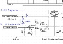
Yes, you could use the 'any shunts' line to detect when a shunt is full on, indicating maximum allowable voltage on the first cell. Normally the control circuit is off during discharge, but you could either power it or make a simple interface to look at the any shunt line. I'll have to study the schematic to see how this would work, but I'm pretty sure you could do something with a diode and a couple of resistors and a transistor.

Once any cell comes up to max, what would you want for the output? Something like an open collector that pulls down? Other option would be a line that is normally low and goes high when you need to cut regen.
 
fechter said:
Once any cell comes up to max, what would you want for the output? Something like an open collector that pulls down? Other option would be a line that is normally low and goes high when you need to cut regen.
Either way would work, since I can program the controller I/O pin to act on either level. So whatever is easier and/or requires less parts and mods to the BMS really.
Thanks for checking this out, Richard! I think such a signal would help make regen a safe experience for the battery, along with good current limiting during regen of course.
 
There are a few ways to do this.
One way would be to isolate the 12v bus line and the any shunts line with diodes so you can supply the line separately from the charging circuit. You would need to supply a voltage (like 5v or 12v) from the controller that would get pulled down by the optocouplers when a shunt goes full. The signal on the any shunts line would be normally high and go low when you need to kill the regen. You would need to cut the traces on the board and jump the cuts with diodes.
Ver 2_3 Regen interface 1.jpg

Plan "B" would involve powering the control circuit whenever the controller is on. This would drain about 10ma or so. Once the control circuit is powered, the any shunts line will be pulled up by the BMS. To backfeed the voltage regulator, you can tie in a single diode and find some voltage supply from the controller that's in the allowable range. I think 5v would be too low. 12v would work, but the normal state for the any shunts line will be a few volts lower due to drop in the regulator. I'm not sure how high you can go on the regulator input. In theory, the regulator transistors can take full pack voltage, but the heat dissipation will be too much for continuous operation. You could put full pack voltage through a resistor and feed the the regulator. If the resistor is chosen so the regulator input is in the happy range, heat should not be an issue.
 
Sorry if this question has already been answered, but the number of pages on this thread have become daunting to read the whole thing. If I make a 24 channel BMS based on these instructions that would be 1 channel for each cell, correct? Is that regardless of if they are hooked up in series or parallel? I have the 16 cell 48v10ah lifebatt pack that would just need 1 16 channel BMS, correct? I also have a lot of a123 cells that I would like to make a 48v10ah pack out of, but that would require 64 cells (correct me if I'm wrong with that calculation) and that would require 64 channels of BMS, right? If that is right then I would need basically 3 BMS units. Or am I completely wrong and you only need one channel per series string or something like that?
 
Does anyone know of another place to get the BOM items from besides mouser.com? Some of them are on backorder.
 
Jay64 said:
(correct me if I'm wrong with that calculation) and that would require 64 channels of BMS, right? If that is right then I would need basically 3 BMS units. Or am I completely wrong and you only need one channel per series string or something like that?

Wrong.
If you are building a series/parallel pack, you only need to count the series cells. It does not matter how many parallel you use. A 48v pack of any capacity would need 16 channels.

DigiKey and Allied are alternate sources for parts. Mouser also has slightly different parts that can be substituted for the backordered ones.

Yes, this thread is incredibly long. Eventually I'll try to do a summary of the technical points.
This thread will contain most of it eventually:
http://endless-sphere.com/forums/viewtopic.php?f=14&t=8140
 
fechter said:
This thread will contain most of it eventually:
http://endless-sphere.com/forums/viewtopic.php?f=14&t=8140

Thanks fechter! That'ld help me out. Nice to see the connections to the battery and charger too, makes it less confusing for us EE noobs!
 
Back
Top