
You are using an out of date browser. It may not display this or other websites correctly.
You should upgrade or use an alternative browser.
You should upgrade or use an alternative browser.
Even Newer 4 to 24-cell Battery Management System (BMS)
- Thread starter GGoodrum
- Start date
methods said:EDIT: Remember to put a standard diode (really any diode) in line between the BMS line and the Throttle line. You will point the arrow of the diode from the Throttle to the BMS. This means that you are hooking the anode to the throttle and the cathode to the BMS. This will stop any positive voltage from leaving the BMS and entering your throttle while at the same time allowing the BMS to "Sink" all the current from your throttle rendering it useless. Look up the CA instructions for another description. The Cathode is the end of the diode with the stripe.
Since the LVC optocouplers can't source any voltage, you really don't need a diode, but a 1k resistor between the throttle and controller is a good idea. In the diagram below, ignore the +5v line and the diode.

michaelplogue said:One other thing: I tried wading through the earlier posts of this thread, but it got to technical for me and had to throw in the towel. However, earlier on you mentioned using a loopback setup added to the charger plug as shown in your illustration (below). Is this still necessary with the current version of the board?
Yes, there is still a jumper in the charger plug, but it has been modified so that one side is common with the charger neg. so that only a 3 pin connector is needed and nothing bad happens if the jumper wire touches the wrong pin.
ejonesss said:ggoodrum do you have a closeup image of
....
but for the version 2.2?
thanks
I don't have it on this computer, but that area on the 2.2 board looks the same.
The only change from 2.1 is in the control circuit jumper.
GGoodrum
1 MW
I'm so sorry about not getting the instructions done yet. My "other" job got real busy the last couple of days. Anyway, I'm on the last page, updating the charger connection section. I'm doing a new version of the illustration shown above. To answer the question, the loopback jumper is not now required, just a separate ground connection for the charge control logic. I will get this done within the hour, and posted.
The control section of the 2.2 version has the extra parts to implement the "3-wire" charger connection, but is otherwise the same as 2.1.
As for the regen issue, pulling down the throtlle line should not require a diode. There's no "voltage" coming out of the BMS board. All the outputs are simply ganged together opto outputs from each channel. These are completely isolated from the rest of the BMS.
-- Gary
the 2.1 image has a hole by it's self leading to a 3 pin part u1 witch i (think ) is the voltage regulator 1 pin leads to the hole witch is on the left below the copyright tppacks.com on the board.
the 2.2 board does not have that hole .
and some of the placement of the parts appear to be different.
that is the main reason i am unable to get started with assembly i would hate to botch up the board if i mess up the assembly.
there is a shot of the 2.2 art unfortunately it is too low bitrate to get a good view of that section.
thanks for any help.
later i will scan and post a picture of the board in good enough detail that if anyone has success with assembly maybe they can point out some of the things better.
fechter said:ejonesss said:ggoodrum do you have a closeup image of
....
but for the version 2.2?
thanks
I don't have it on this computer, but that area on the 2.2 board looks the same.
The only change from 2.1 is in the control circuit jumper.
GGoodrum
1 MW
Here, this might help:

better than nothing unfortunately with all of the parts being so close together it makes it difficult to figure out what is what i think a vector art eps format would help better.
otherwise i will wait until you get the instructions complete and sent out.
also jpg gives a higher quality than bmp for the size.
otherwise i will wait until you get the instructions complete and sent out.
also jpg gives a higher quality than bmp for the size.
GGoodrum said:Here, this might help:
GGoodrum
1 MW
Here are the completed instructions: 4/24-cell BMS Assembly and Test Instructions.
i see a problem with page 5.
you used an assembled version 2.1 board you should be using a 2.2 board because there are some changes that are confusing.
is the only differences between version 2.1 and 2.2 board is just the placement of the charger wires?
is the placement of the other parts unchanged between versions 2.1 and 2.2?
GGoodrum said:Here are the completed instructions: 4/24-cell BMS Assembly and Test Instructions.
Here's a parts side view in a slightly higher res. The bottom side traces have been removed so this represents what you would actually see on the top side. (click on the picture to enlarge)

Malcolm
10 kW
Big thanks to Gary and Richard! Parts are on their way. New soldering station is ready and waiting. I'm looking forward to making a start.
GGoodrum
1 MW
Patriot said:Gary,
Just curious if you got the new boards in yet.
(currently printing instructions)
Yes, the second batch came in late yesterday. These will be going out today.
GGoodrum
1 MW
ejonesss said:i see a problem with page 5.
you used an assembled version 2.1 board you should be using a 2.2 board because there are some changes that are confusing.
is the only differences between version 2.1 and 2.2 board is just the placement of the charger wires?
is the placement of the other parts unchanged between versions 2.1 and 2.2?
GGoodrum said:Here are the completed instructions: 4/24-cell BMS Assembly and Test Instructions.
All I had of an assembled board was one that Richard sent me of his 2.1 version board. I don't even have one of those. My last assembled board is the v1.5 version that is on one of my bikes. If I can ever get to the point that I'm not getting 5 PMs a day, and countless emails asking questions about when the boards and/or instructions are going to be ready, maybe I'll have time to actually build one of these.
")
Anyway, the only difference between the 2.1 and 2.2 boards is the addition of three parts to the 12V regulator part of the charge control circuit. These allow the elimination of the two-wire jumper, so that all that is needed is an extra ground wire to power the charge control logic. The individual channels are identical.
-- Gary
rkosiorek
100 kW
i thought this was to be a DO IT YOURSELF type of thing. i am very happy with the level of information supplied by Both Richard Fechter and Gary Goodman. they have both invested way more time and energy into designing and testing these boards then they will ever make by selling these boards. if we had to pay them by the hour we could never afford these boards. the level of documentation supplied equals or exceeds that provided by many other board level kits i have purchased.
a big heartfelt thanks to both of you guys.
i am also hoping that there is a bit of a language barrier in interpreting the comments by "ejonesss". in his own way he may attempting to contibute in the only way he can. he may just be suggesting on how to improve the instructions/documentation in future iterations and not demanding that the changes be made now.
though i have to admit that on first read i also reacted to his comments by thinking - "How Rude! Some people always want to push the envelope. like they aren't getting a value already?"
but then i got a surprise visit from an old friend. she is always trying to improve me so we spent some time meditating, exploring ourselves and sleeping on our problems. she has a way of relaxing me and forcing me to look for the good in everyone. after waking up in the morning i re-eveluated my initial opinion of the "ejonesss" comments and decided that he must be trying to help, that his were comments, not harsh and whinning criticism.
rick
ggoodrum and fechter i nearly got done installing the resistors and getting ready to install the capacitors and i discovered another mistake in the instructions or board.
the board calls the 0.1 (.1 uf) capacitor as c4 the instructions call it c3 it is the one next to the gate driver chip u2.
other than that and a few accidental hole cover up i am doing pretty good so far.
the board calls the 0.1 (.1 uf) capacitor as c4 the instructions call it c3 it is the one next to the gate driver chip u2.
other than that and a few accidental hole cover up i am doing pretty good so far.
GGoodrum
1 MW
ejonesss said:ggoodrum and fechter i nearly got done installing the resistors and getting ready to install the capacitors and i discovered another mistake in the instructions or board.
the board calls the 0.1 (.1 uf) capacitor as c4 the instructions call it c3 it is the one next to the gate driver chip u2.
other than that and a few accidental hole cover up i am doing pretty good so far.
The instructions are right. On the next version of the board, I'll change it. For the 1% of the people that can't figure it out, I'll let them know.
is there a way to power the charging circuit with a 12 volt power supply so i can test the charging of 1 cell on each channel?
meaning can i just connect a 12 volt power supply to the 12 volt bus?
theoretically 12 volts should be enough to charge 1 cell.
meaning can i just connect a 12 volt power supply to the 12 volt bus?
theoretically 12 volts should be enough to charge 1 cell.
ejonesss said:is there a way to power the charging circuit with a 12 volt power supply so i can test the charging of 1 cell on each channel?
meaning can i just connect a 12 volt power supply to the 12 volt bus?
theoretically 12 volts should be enough to charge 1 cell.
Yes.
Yes.
Yes.
In fact, this is actually a good point since lots of us have small power supplies that can do 12v.
Actually, you need more like 15v to run 4 cells. You can then test the first 4 cells and power the voltage regulator. The first 4 cell LEDs should light. If you have a little more voltage available, you can try 5 or 6 cells.
Once you verify that the first 4 are working, then you can go up the chain using a jumper clip to power each cell circuit above 4, one at a time.
To test a single cell circuit, you'd need one 12-15v supply for the control circuit and another one to power the cell circuit(s). One cell is not enough voltage to run the control circuit.
It is a real good idea to test the circuit using a current limited variable power supply if you have one available. This way if there's a shorted trace or something, the likelyhood of getting smoke is much reduced. Once you test everything with a power supply, then you could try using the charger to see if you can light all the LEDs and get it to trip into the automatic shutoff mode.
Some chargers won't initiate output without some voltage being present. In this case, you can use the battery to 'jump start' the charger. You could touch it for just a second or connect it through a current limiting device, like a light bulb. Once the charger starts output, most of them will stay on.
Only connect actual batteries to the thing after you have tested everything.
Some chargers won't initiate output without some voltage being present. In this case, you can use the battery to 'jump start' the charger
that is the description of an anti spark charger like the deka power sports charger.
sparks around a lead acid battery especially when venting gas is bad the battery can explode the sealed ones like used in alarms are safer to work with.
correct me if i am wrong but since the 12 volt bus needs 12 volts it is possible to use a computer power supply's 12 volts to the board and only charge 1 cell.
my idea is so i do not have to connect all 4 cells on a 12 volt test. i would apply 12 volts then connect a cell or maybe a large capacitor instead of a cell (because capacitors can be charged and discharged faster maybe use a power filtering or camera flash cap).
if you need the 15 volts you can connect across the minus 12 and the plus 3.3 rail of a computer power supply.
you may get slightly less if the 12 or minus 12 rails are only putting out 11.xx instead.
the idea is the minus voltages are rated for less than 1 amp and are easily tripped.
fechter said:ejonesss said:is there a way to power the charging circuit with a 12 volt power supply so i can test the charging of 1 cell on each channel?
meaning can i just connect a 12 volt power supply to the 12 volt bus?
theoretically 12 volts should be enough to charge 1 cell.
Yes.
Yes.
Yes.
In fact, this is actually a good point since lots of us have small power supplies that can do 12v.
Actually, you need more like 15v to run 4 cells. You can then test the first 4 cells and power the voltage regulator. The first 4 cell LEDs should light. If you have a little more voltage available, you can try 5 or 6 cells.
Once you verify that the first 4 are working, then you can go up the chain using a jumper clip to power each cell circuit above 4, one at a time.
To test a single cell circuit, you'd need one 12-15v supply for the control circuit and another one to power the cell circuit(s). One cell is not enough voltage to run the control circuit.
It is a real good idea to test the circuit using a current limited variable power supply if you have one available. This way if there's a shorted trace or something, the likelyhood of getting smoke is much reduced. Once you test everything with a power supply, then you could try using the charger to see if you can light all the LEDs and get it to trip into the automatic shutoff mode.
Some chargers won't initiate output without some voltage being present. In this case, you can use the battery to 'jump start' the charger. You could touch it for just a second or connect it through a current limiting device, like a light bulb. Once the charger starts output, most of them will stay on.
Only connect actual batteries to the thing after you have tested everything.
i have another discrepancy between the board and instruction.
the board calls for q2 witch is the 511-STP160N75F3 mosfet to be in the 3 holes below the copyright 2008 tppacks.com etched.
but logic calls for it to be mounted in the large pad next to the copyright etching.
i placed it on the pad next to the copyright etching but if that is wrong please let me know i do have a desoldering iron so i can remove the part.
also i see that the instructions have Q1, Q3 2N3906 transistor
but on the board there is only Q1 and Q2.
Q1 is in the corner of the board below scr 1.
i am down to just installing the Ux02 LM431 2.5V linear regulator and the 16 large power resistors.
The Mosfet legs go into the 3 holes and the tab is screwed onto the large pad, which acts as a heat sink. The pad connection and the middle leg are redundant. Look at the picture of the completed board.
Both the bipolar transistors are 2N3906. We'll correct the numbers next pass.
I think you could test using a computer power supply's -12 and +5 (17v). Remember that most computer supplies need a hefty load to stay running. This usually requires a big 10w resistor across the +5 or +12 output.
You don't need to use a capacitor as a battery simulator for testing, but you could if you wanted to. I just test them with nothing attached.
when you have no battery connected are the channel leds supposed to lit?
because only the master led is lit red when the 12 volt supply is connected.
none of the channel leds are lit.
i am using a 12 volt scanner wall wart witch is rated at 1.25 a and puts out 12.25 volts
when a single cell was connected to a channel and the lvc test pads are shorted nothing happens no lighting of the channel leds.
are the channel leds supposed to light when it hits lvc?
do i need an inital 12 volt to the charger circuit for control?
my understanding of the schematic is the channel; leds are connected such that when the lvc comes on it the leds light to indicate what cell is low.
fechter said:The Mosfet legs go into the 3 holes and the tab is screwed onto the large pad, which acts as a heat sink. The pad connection and the middle leg are redundant. Look at the picture of the completed board.
Both the bipolar transistors are 2N3906. We'll correct the numbers next pass.
I think you could test using a computer power supply's -12 and +5 (17v). Remember that most computer supplies need a hefty load to stay running. This usually requires a big 10w resistor across the +5 or +12 output.
You don't need to use a capacitor as a battery simulator for testing, but you could if you wanted to. I just test them with nothing attached.
The cell LEDs only light up when the shunts are on. There is no indicator for the LVC.
Getting the red status LED to light with 12v is good.
12v is not enough to light up 4 cells. You might try jumpering one so that only 3 are getting juice and see if you can make the status LED go orange/greenish.
The board is really big for a bike pack already. We want to make it smaller by using surface mount parts. :wink:
Yes, you do need to pay attention to the polarity of most of the parts. The LEDs have a flat side which is indicated on the layout diagram.
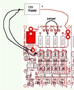
Here's a diagram to partially test the circuit with a 12v supply:
The jumper will bypass one cell in the middle so the other 3 have enough juice to light up.
You can move the jumper to test the bypassed cell.
If you have more than 12v available, you can try to light up more cells. By moving the jumper around, you can test all of the cells.
When you have the LEDs lit up, you should see the red status LED go slightly greenish. If you use a small screwdriver and short the output pins on the optocoupler for the shunts, you should see the status LED go solid green while shorting.
Attachments
Similar threads
- Replies
- 64
- Views
- 21,780
- Replies
- 6
- Views
- 3,956
- Replies
- 10
- Views
- 34,598
- Replies
- 58
- Views
- 33,132
- Replies
- 12
- Views
- 5,823