I don't think scaling it down will help with the simulation.Farfle said:I wonder if scaling it down would at least get me in the ballpark with magnet coverage for a given stator configuration, and then I can refine the flux densities in FEMM.
You are using an out of date browser. It may not display this or other websites correctly.
You should upgrade or use an alternative browser.
You should upgrade or use an alternative browser.
Farfle's Mk.5 Super badass outrunner
- Thread starter Farfle
- Start date
If you run 2 in series you get a little more inductance than a Colossus.Farfle said:hmm, emetor is spitting out 0.005797 mH or 5.7uh. thats really really really low. bugger.
Back to the drawing board!
major
10 kW
Using bars in the slots is similar to this:  From: http://www.ecycle.com/Brushless_Motor_Technology.html Unfortunately that website no longer shows much in the way of construction details. Welding the bars in place as you intend will be difficult if not impossible. Remy has developed a good method of welding hairpin coils called HVHP. They end up with 4 coil sides pet slot. And as you noted, use a higher slot count.
From: http://www.ecycle.com/Brushless_Motor_Technology.html Unfortunately that website no longer shows much in the way of construction details. Welding the bars in place as you intend will be difficult if not impossible. Remy has developed a good method of welding hairpin coils called HVHP. They end up with 4 coil sides pet slot. And as you noted, use a higher slot count.Farfle
100 kW
Ok, after giving another shot, and blowing thru 45 emetor credits at 7 credits per sim. I think I have a final design. Its 12t 10p in a dual-layer configuration, which works well as far as BEMF goes (I can not actually simulate this one, but its a WAG based on tests of 12t 8p and 12t 16p) .
Overall weight minus sidecovers and axle is 45lbs. so probably 65lbs when copper, axle/bearings and sideplate go on. phase conductor area is ginormous, so copper loss should be minimal at 1000A. And because the magnets have an awesome cooling path to the outside, I used segmented n52 magnets, even though they have a lower temperature failure point.


Overall weight minus sidecovers and axle is 45lbs. so probably 65lbs when copper, axle/bearings and sideplate go on. phase conductor area is ginormous, so copper loss should be minimal at 1000A. And because the magnets have an awesome cooling path to the outside, I used segmented n52 magnets, even though they have a lower temperature failure point.


(I can not actually simulate this one, but its a WAG based on tests of 12t 8p and 12t 16p)
It fails? does it give a reason?
I have had problems with failed simulation when the tips of the teeth are too thin. If you increase the gap between tips, and maybe increase tip size a bit, it may work. It looks like the end of the teeth aren't of much help anyway.
I've also had problems with failed simulations which starts to work when the airgap was is increased. Have you asked Emetor for help?
Motor looks nice. You should simulate it with load. It looks like the tip angles are a bit too small. Under load the tips will see more flux.
I think it's just the single winding symmetry.bearing said:It fails? does it give a reason?
What will you use for the stator/rotor laminations? Have you had a quote for Hiperco 50?
Just a small suggestion: Assuming the rotor is laminated, you could give it a more rigid structural form. Bearing in mind the single symmetry and relatively high speed......
Just a small suggestion: Assuming the rotor is laminated, you could give it a more rigid structural form. Bearing in mind the single symmetry and relatively high speed......
Miles said:I think it's just the single winding symmetry.bearing said:It fails? does it give a reason?
20p24t worked for me (at least the load sim), so this should work. Or am I wrong?
Farfle, are you using single or double layer windings?
Double layer seems to simulated easier as well.
24t 20p has two symmetries. 24t 22p, which has only one, fails for me.bearing said:Miles said:I think it's just the single winding symmetry.bearing said:It fails? does it give a reason?
20p24t worked for me (at least the load sim), so this should work. Or am I wrong?
bearing said:Farfle, are you using single or double layer windings?
Double layer seems to simulated easier as well.
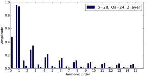
A single layer 12t 10p has quite a dominant sub-harmonic, too......Farfle said:I think I have a final design. Its 12t 10p in a dual-layer configuration
So, a nice round target of 100Nm to meet the Challenge...Farfle said:so probably 65lbs when copper, axle/bearings and sideplate go on.
")
Something like this...Miles said:Just a small suggestion: Assuming the rotor is laminated, you could give it a more rigid structural form. Bearing in mind the single symmetry and relatively high speed......
Not so good for heat dissipation, unless you only do it on alternate lams....
Attachments

Miles said:24t 20p has two symmetries. 24t 22p, which has only one, fails for me.
Still seems strange. The reason 20p24t has two symmetries is that it's "two 10p12t". So the 20p24t sim will only run on half the motor. And that half has 10p and 12t.
I think the simulation fails if there are too many triangles in the mesh or similar. Just a guess. But it seems likely, since the reason for the fail was that it run out of memory.
When you change the dimensions of the tips, you get a new mesh, so I may have been just above the limit when I fixed it by increasing some tip dimension, which probably made a less dense mesh around the tips.
I have been able to simulate 8p9t, which has only one winding symmetry.
Have you done it since the changes to the airgap meshing, though?bearing said:I have been able to simulate 8p9t, which has only one winding symmetry.
Maybe it's a combination of factors? 12t 10p is over 360 degrees, rather than 180 degrees, so perhaps this requires a bigger mesh (more elements)?
I didn't know about an airgap meshing change. But sims that used to run, doesn't anymore, so that makes sense. I thought it was because he made a limit on the free simulations (I'm out of credits).
That's possible. If the limit is the amount of elements, then I guess almost all variables are involved.
That's possible. If the limit is the amount of elements, then I guess almost all variables are involved.
bearing said:I didn't know about an airgap meshing change.
"The implementation of the new breadloaf magnet template was not that straight-forward as first expected. Since the surface radii of the breadloaf magnets now no longer coincide with the rotor radii, the generation of the finite elements in the airgap had to be reimplemented. Well, to make a long story short, the airgap is now divided into three equidistant layers (as opposed to two layers previously). And the simpler Delaunay triangulation previously used for meshing the airgap, has been replaced by the same mesh generator that was already used for generating the rest of the mesh. The torque determination based on Maxwell's stress tensor is now performed on the middle airgap layer only, resulting in an even better agreement with the torque calculated from the flux linkages and currents."
Ref: https://www.emetor.com/blog/post/release-2013-10-18-more-flexible-template-breadloaf-magnets/
John in CR
100 TW
20p24t will also run on half the teeth at 20p12t. Then use 2 sets of halls and dual controllers for a smoother running 6 phase with 20p12t12t and the 12's wound on every other tooth.
Farfle
100 kW
Miles said:What will you use for the stator/rotor laminations? Have you had a quote for Hiperco 50?
Just a small suggestion: Assuming the rotor is laminated, you could give it a more rigid structural form. Bearing in mind the single symmetry and relatively high speed......
I am wondering if the back iron needs to be laminated, and if it doesn't, I would machine it from a single piece of 12" dia, .5"wall 1018 tubing (304.8mm dia x12.5mm wall. Which is actually pretty cheap.
The minimum wall thickness in this sim is 6mm.
I have not looked for a quote on hiperco 50 yet. But I am assuming that it is at least purchaseable.
And JohninCR, this motor can be run as 6 phase. 6p6p10t
Farfle
100 kW
Miles said:So, a nice round target of 100Nm to meet the Challenge...Farfle said:so probably 65lbs when copper, axle/bearings and sideplate go on.
Emetor was giving me 250n/m at 1000A. .25nm/a is 400a cont. Piece of cake 8)
I doubt it will make a major difference and it's heat generated within the magnets themselves that is the greater threat..... You're segmenting the magnets circumferentially. How about axially?Farfle said:I am wondering if the back iron needs to be laminated, and if it doesn't, I would machine it from a single piece of 12" dia, .5"wall 1018 tubing (304.8mm dia x12.5mm wall. Which is actually pretty cheap.
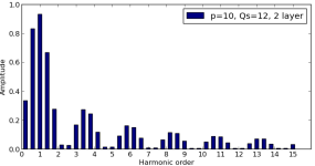
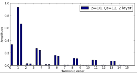
The worst of the sub-harmonics is cancelled out in 3 phase:
Attachments
Farfle
100 kW
Miles said:I doubt it will make a major difference and it's heat generated within the magnets themselves that is the greater threat..... You're segmenting the magnets circumferentially. How about axially?
The worst of the sub-harmonics is cancelled out in 3 phase:
Yes, the magnets will be both axially, and circumfrentially segmented. I am thinking of doing them in 20mmx20mmx5mm squares. I believe that will play nice during assembly. Ill probably cut out and stack an alignment jig out of lexan with the schools lil laser.
And it seems your links are broken miles