

-
Hello ES! We could use some help to get us past the finish line on building the new knowledgebase for the forum.
Can you donate? Please see our fundraising page. Thank you!
You are using an out of date browser. It may not display this or other websites correctly.
You should upgrade or use an alternative browser.
You should upgrade or use an alternative browser.
FarGrin -- Time to push some amps
- Thread starter chuyskywalker
- Start date
slaphappygamer
🚴♂️ Mega poster
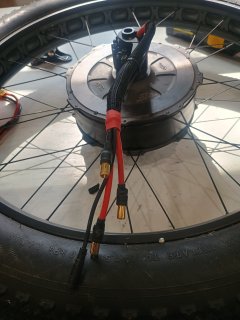
Nice. I like how you kept the hall sensor wires tidy.View attachment 376347
I'm with you on pushing some amps to this motor. 150 phase amp is the max i went so far but i still had the L1019 on it. I should be good now for a bit more now.
Did you splice those phase wires at the axle? Or do they go into the motor?
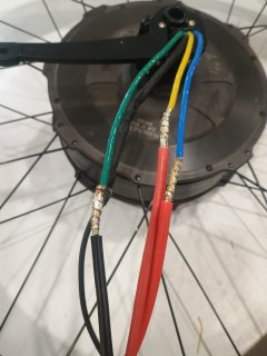
I cut the PAS cable out and reused it for the halls and left some of the original phase wires. During testing they barely got warm at 150a short bursts. At my normal cruising speed they should only see 30-40a continuous. They can breath better now as well
Last edited:
slaphappygamer
🚴♂️ Mega poster
Looks great!
I was thinking about doing something similar to my motor, but decided not to after I saw decent temps at various locations along my commute. Motor never reached more than 82C.
How did you wrap the wires? Looks like the mesh is the only wrap and the red heat shrink at the ends.
I was thinking about doing something similar to my motor, but decided not to after I saw decent temps at various locations along my commute. Motor never reached more than 82C.
How did you wrap the wires? Looks like the mesh is the only wrap and the red heat shrink at the ends.
Double wall adhesive Shrink tube over the splices and a couple of spots i used electrical tape to keep things tight before i put the mesh onLooks great!
I was thinking about doing something similar to my motor, but decided not to after I saw decent temps at various locations along my commute. Motor never reached more than 82C.
How did you wrap the wires? Looks like the mesh is the only wrap and the red heat shrink at the ends.

chuyskywalker
🚴♂️ Mega poster
I'm stunned you didn't turn the L1019 into a goopy mess pushing 150a through it! I kinda recall Grin calling it out as "not happy" somewhere around 80 or something I think.150 phase amp is the max i went so far but i still had the L1019 on it.
Then again, amps coming in bursts vs. long hauls make a big difference. There's a few hills around here that are just nothing but incline all day long that I'll be using to torture test my setup eventually. One of them even claimed a motor of mine previously, lol.
I'll be putting XT150's on my connections once I get that sorted out. I do like the ideal of snipping the PAS cable out to reuse for the halls -- pretty smart reuse of something I won't be touching

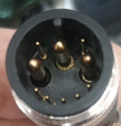
One mistake i made was not using that end on the controller side because it has male pins that could get bent if not plugged in right. In my case replacing the plug on the controller would be far quicker. I also started with xt150s. Got one soldered and didn't like how little of wire goes in the end so I cut open some qs8 connectors and used them
chuyskywalker
🚴♂️ Mega poster
Ah, good reminder! I don't normally have these in my bag'o'goodies, but for this build it'd be good to have for the battery/controller interconnect. (Spec wise, the qs10 is probably "righter", but I think the 8's will do fine.)Got one soldered and didn't like how little of wire goes in the end so I cut open some qs8 connectors and used them
Are you talking for battery connection or phase wires? I used the qs8 on my qs205 motor for phase and battery and never had a problem. What are we thinking the windings in the max45 can handle for short bursts and saturation level?Ah, good reminder! I don't normally have these in my bag'o'goodies, but for this build it'd be good to have for the battery/controller interconnect. (Spec wise, the qs10 is probably "righter", but I think the 8's will do fine.)
I had asked Hayley at Grin this question last year and didn't get a straight answer, but their promo video shows them testing it with an ASI BAC4000 at "300+A" of current.What are we thinking the windings in the max45 can handle for short bursts and saturation level?
chuyskywalker
🚴♂️ Mega poster
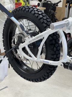
Tires and tubes arrived.
I have put on a good number of tires in my time. Some of the worst have stressed my very mind, body, and soul (never, EVER again, 8" solid scooter tires).
The shinkos... my goodness, one of the easiest, smoothest installs I've ever had (for new tires). Slight application of soapy water and they rolled right over the rim edges with bare hand pressure. The tire irons sat, forlorn, upon the floor their services unneeded.
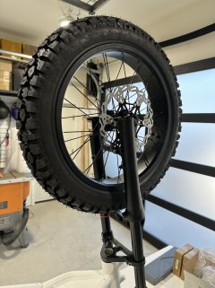
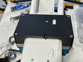
I also got the controller mount modeled and 3d printed. Took a few tries to get the measurements sorted out, as is normal.
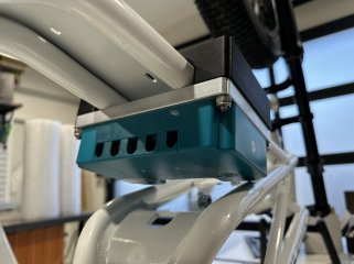
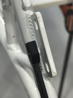
And now that it has tires and a kickstand, I can get it upright
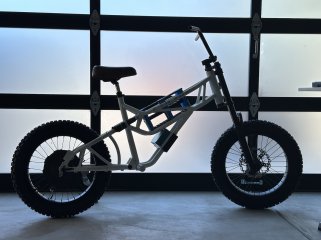
Also tossed on a seat, the pegs, and the 203 rotors.
I have put on a good number of tires in my time. Some of the worst have stressed my very mind, body, and soul (never, EVER again, 8" solid scooter tires).
The shinkos... my goodness, one of the easiest, smoothest installs I've ever had (for new tires). Slight application of soapy water and they rolled right over the rim edges with bare hand pressure. The tire irons sat, forlorn, upon the floor their services unneeded.
I also got the controller mount modeled and 3d printed. Took a few tries to get the measurements sorted out, as is normal.
And now that it has tires and a kickstand, I can get it upright
Also tossed on a seat, the pegs, and the 203 rotors.
chuyskywalker
🚴♂️ Mega poster
Sadly, no. The TA would have to bend to make that work, and that's a big no-no direct from grin.
I think the arm on the triangle frame piece will be fine.
I think the arm on the triangle frame piece will be fine.
OkinawaJapan
🔋 Established
- Joined
- Jun 17, 2012
- Messages
- 57
Some great pics. Tires look strong. Liking the controller mount and pegs. Looking like a beast already.
What size are the Shinkos? 110/70=16? And which Weinmann rims? I may grab these later. They look phenomenal.
What size are the Shinkos? 110/70=16? And which Weinmann rims? I may grab these later. They look phenomenal.
chuyskywalker
🚴♂️ Mega poster
I got them off revzilla; labeled as "Shinko 244 Dual Sport Tires Front/Rear, 3.00x16 45P".What size are the Shinkos? 110/70=16? And which Weinmann rims?
The front rim is, uh, whatever the frame maker uses, and the rear is one of the fat rims from grin ("Rim20_Fat_32H").
---
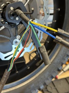
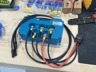
Swapped out the motor to XT150's and repurposed the pas connection for halls + temp. The controller side also got the phase wires and a battery wire setup put in place.
Fun fact -- the QS8 connector is too large to go through the frames "battery comes through here" cutout. Will have to route it some other direction
chuyskywalker
🚴♂️ Mega poster
It's alive!
Lots of wiring left to do...and, ya know, a whole battery build.
Lots of wiring left to do...and, ya know, a whole battery build.
chuyskywalker
🚴♂️ Mega poster
Starting the wire up. Could not figure out this moto switch set (horn/blinkers/light). Had to take it apart to determine which wire was what:
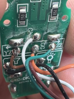
Whoever decided white should be a ground color when there is a black in the bundle needs a good slap upside the head.
With that sorted out, it was time to go about the blinker and light mounting. The headlight will be a simple clamp-on-bar setup, but the blinkers and rear brake light are slightly more complicated because there's nothing much really built in for that. Off to one of my favorite hobbies, Fusion and 3D Printing!
The brake light is pretty straight forward -- mostly just a clamping, bolt-through structure the size of the brake light with one minor complication that the clamping "cut out" should be angled to point the light a little more level.
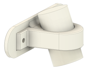
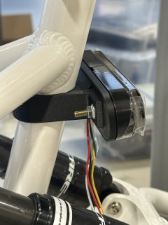
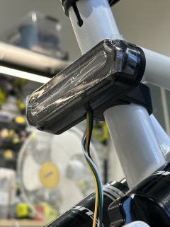
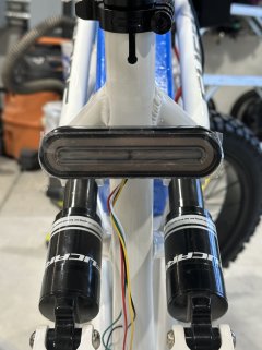
Came out great! Could use some small rubber inserts to keep it from rotating (PETG is pretty slippery on the paint finish). Otherwise, came out nicely. The light has built in "flowing" blinkers (in the middle), a running light, and flashes+brightens on brake activation. (There's even a "start up" animation thing it goes through, which I could live without, lol.)
---
For the front of the bike, I need a place to mount the turn signals but I also need a place to organize all the wire mess. There's at least 13 wires being pulled to the handlebars (12v, throttle, 3 way, brakes, voltmeter, display, key, return 12v from brakes, etc, etc).
I modeled up a "box" to sit between the stanchions which could have the blinkers on the sides, easy access to the contents, wire entrances, poke the horn out, and be easy to work in:
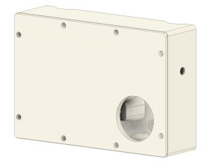
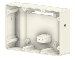
There's a simple clamp structure on the back at all four corners to hold it on. I just undersized the holes on the box at about 4.6mm and use a drill to self-tap-drive in M5 bolts. Works really well, and now the holes are threaded. Won't stand up to huge torque or a million in/out operations, but saves me the time doing heat-set inserts and will hold up fine. (And if it doesn't easy fix, just reprint and add inserts.)
Came out pretty well:
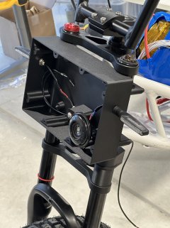
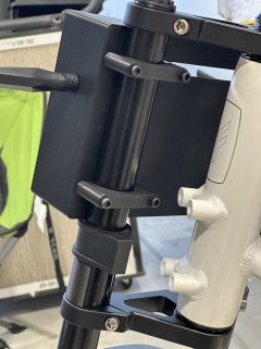
The arches were a bit goofy to print (support material) since it's printed with the back on the print surface, but you also can't see any of the left over mess since it's hidden by the fork, so ha!
I'm also gonna pat myself on the back -- got both of these to fit and work on the first print. Noice.
Whoever decided white should be a ground color when there is a black in the bundle needs a good slap upside the head.
With that sorted out, it was time to go about the blinker and light mounting. The headlight will be a simple clamp-on-bar setup, but the blinkers and rear brake light are slightly more complicated because there's nothing much really built in for that. Off to one of my favorite hobbies, Fusion and 3D Printing!
The brake light is pretty straight forward -- mostly just a clamping, bolt-through structure the size of the brake light with one minor complication that the clamping "cut out" should be angled to point the light a little more level.
Came out great! Could use some small rubber inserts to keep it from rotating (PETG is pretty slippery on the paint finish). Otherwise, came out nicely. The light has built in "flowing" blinkers (in the middle), a running light, and flashes+brightens on brake activation. (There's even a "start up" animation thing it goes through, which I could live without, lol.)
---
For the front of the bike, I need a place to mount the turn signals but I also need a place to organize all the wire mess. There's at least 13 wires being pulled to the handlebars (12v, throttle, 3 way, brakes, voltmeter, display, key, return 12v from brakes, etc, etc).
I modeled up a "box" to sit between the stanchions which could have the blinkers on the sides, easy access to the contents, wire entrances, poke the horn out, and be easy to work in:
There's a simple clamp structure on the back at all four corners to hold it on. I just undersized the holes on the box at about 4.6mm and use a drill to self-tap-drive in M5 bolts. Works really well, and now the holes are threaded. Won't stand up to huge torque or a million in/out operations, but saves me the time doing heat-set inserts and will hold up fine. (And if it doesn't easy fix, just reprint and add inserts.)
Came out pretty well:
The arches were a bit goofy to print (support material) since it's printed with the back on the print surface, but you also can't see any of the left over mess since it's hidden by the fork, so ha!
I'm also gonna pat myself on the back -- got both of these to fit and work on the first print. Noice.
Last edited:

The wiring color choices I've seen....Whoever decided white should be a ground color when there is a black in the bundle needs a good slap upside the head.

chuyskywalker
🚴♂️ Mega poster
There are some more specific dates back in the thread, but about 30 days.How long was the shipping?
Furcare makes some neat trellis bike designs.
chuyskywalker
🚴♂️ Mega poster
Today's updates:
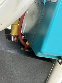
1) Controller area wire mess "contained". This box was...complicate to make. It's a weird shape in this space. Plus there's a lot of weird cutouts needed for wire routing. I only attached one support on the back, but it seems pretty stable, plus not a lot of place for it to go.
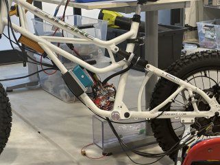
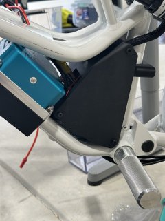
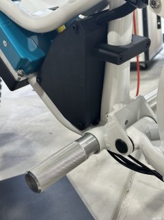
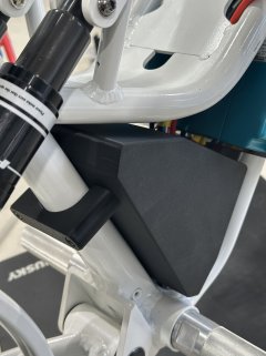
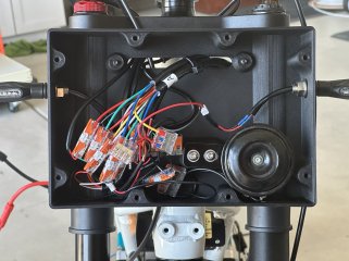
The front box is pretty much done wiring. I also got the display in today, but still working on getting that fully mounted.
Lastly, though, battery time!

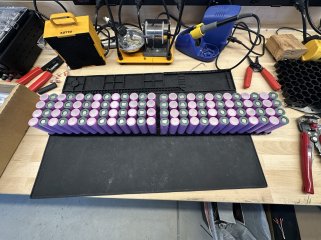
Haven't started welding yet, just laid them out and arranged 'em. Plan is to fold over at the break.
1) Controller area wire mess "contained". This box was...complicate to make. It's a weird shape in this space. Plus there's a lot of weird cutouts needed for wire routing. I only attached one support on the back, but it seems pretty stable, plus not a lot of place for it to go.
The front box is pretty much done wiring. I also got the display in today, but still working on getting that fully mounted.
Lastly, though, battery time!
Haven't started welding yet, just laid them out and arranged 'em. Plan is to fold over at the break.

By arranged do you mean it's their final location? Won't you be measuring them for group allocation?
Neat box btw. Another case where a scanner would be so helpful, I'm so so so close to ordering one... I'll likely go with a composite box for #2 because I can reuse the mold for #1 then.
Neat box btw. Another case where a scanner would be so helpful, I'm so so so close to ordering one... I'll likely go with a composite box for #2 because I can reuse the mold for #1 then.
chuyskywalker
🚴♂️ Mega poster
I did a rough scan with the phone & an app that actually produces something...sorta usable, honestly. If helped a good bit, but still required an iteration or two. I originally wanted to go for just a panel on each side that sorta molded to the curved shapes, but even with the scan, that proved really hard to model and, honestly, I don't think it would have printed particularly well.where a scanner would be so helpful, I'm so so so close to ordering one...
Honestly, no. Between these being factory-fresh cells and given each P group should be able to handle ~240A (4*60) (which I won't come even close to as the controller peaks at 170, and I likely won't have it set that high anyway), it's not worth the time to me.Won't you be measuring them for group allocation?