Faulty new Sunwin controller or me?

mickydido

1 mW
Joined
May 31, 2014
Messages
12
Location
sheffield
Hi
Advise please?
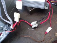
I have just bought a new 48v 1000w Sunwin Controller off EBay
http://www.ebay.co.uk/itm/181128799839?ssPageName=STRK:MEWNX:IT&_trksid=p3984.m1497.l2649

I am thinking its faulty, or is this unlikely? Connections seem fine. I am getting 6v on the small red "ignition/e-lock going in the controller. I am only getting 0.4v at the throttle and likewise at the Hall sensor connector (Black and red) Any ideas please before I contact seller again (He has sent me some extra info and I have found a wiring diagram on Amazon) I am not really that knowledgable!
Thanks
micky
 
Hi
Thanks for suggestion
I have managed to post diagram (Added to first post) and I believe that this is how I have wired mine. That is; A fuse between tthe thin/thick red (Twisted together in connector.) and the positive lead from battery.
I think I tried it without the fuse,( losing track now)

The relevant instructions (below) says the same as you. Should it always show 48v ? (Actually 53v at the battery) I thought it was only low voltage until swithed on? (I do not have a switch)

" Some of the batteries have 3 cables, one of them is the E-door lock cable. This
cable would have the following feature: when switch on the lock by using the bike
key, this cable’s voltage would be tested with value shown on the meter same as the
batteries; when switch it off, the cable will be tested with no voltage result shown"

Thanks for help
 
No fuse is needed there. In fact, the fewer components the better. Some people add a switch or key to that wire, as losing power on that wire shuts down the controller. But you can't use the thin wire as an "Off" switch. even though the controller will be "off" "locked" or otherwise not working, the controller will still be connected to the battery and slowly bleeding off power. If you park your bike with a drained battery at the end of a ride and rely on a switch there to turn it off, the controller may still pull enough power to ruin the battery in a few days to a week.

Yes, it should have full battery voltage, what ever that may be.
 
Drunkskunk said:
No fuse is needed there. In fact, the fewer components the better. Some people add a switch or key to that wire, as losing power on that wire shuts down the controller. But you can't use the thin wire as an "Off" switch. even though the controller will be "off" "locked" or otherwise not working, the controller will still be connected to the battery and slowly bleeding off power. If you park your bike with a drained battery at the end of a ride and rely on a switch there to turn it off, the controller may still pull enough power to ruin the battery in a few days to a week.
Yes, it should have full battery voltage, what ever that may be.

Thanks for that. I am probably being over cautious but still trying to get to grips with fundamental electrics. I bought the battery second hand and I guess the guy disconnected by separating the main connecter
I dont understand why when both thick and thin red wires can carry the same voltage. I assume different current drawn. Would you please suggest the best way to connect to the battery?
(The big picture shows black and red wires on the BMS that are the Kettle socket)
THANKS
 

Attachments

  • sunwin cont (1).JPG
    sunwin cont (1).JPG
    139.9 KB · Views: 2,118
  • sunwin cont (3).JPG
    sunwin cont (3).JPG
    148.6 KB · Views: 2,118
I have managed to connect the small red wire into the battery cconnector (Main plug at battery end) but still only getting 6v (at the end of the brown wire-connector in pic) - baffled! I know I need the 53v.
 
dnmun said:
why do they have a white plastic plug between the BMS and the battery? why is the red B+ lead going into the BMS?

where did that battery come from?

I bought it second hand (EBay) and it had a previous owner, so no paper work. he said it was fronm abroad. It came with a 1000w hub which I have it wired to - on my bench

The little red shows 3v, but when I connect the voltmeter to the black (in connector) I noticed the voltage crept up to 36v and more. Its as if the little red is not connected in the controller

At the connector between the BMS and cotrolller there is 3v, is that normal? presumably you only get the high voltage when it is drawn?

I cant get to the battery terminals but at the first plug its 53v

Hope this makes sense, I,m lost

thanks for thoughts
 
dnmun said:
first thing to fix is the battery and BMS connections and then see if there is really anything wrong with the controller.
do you have soldering iron and 60/40 solder?

Hi and thanks for help

Yes I can solder, do you think the connnections are suspect? Should there be 53v at the treminal block all the time?

Bit complicated but can I please explain.

I really only wanted another battery for my 350w hub (The 1000w hub was with it) For curiousity I connected battery to the 1000w hub on the bench. I used my 36v-48v 350w controller. I just slowly used the throttle and the wheel turned, I did not give full throttle). I was content with that test but I think it still damaged the controller? Tried again since but no go.
I assume from this, that the battery and the hub was ok. That controller did also have the small red wire which I connected to the block alongside the large red.
I have ordered a 48v 350w controller which arrive soon may solve the riddle?
Thanks again
micky
 
the way the battery is wired to the BMS is subjecting the battery to disconnection or possible fire if the B+ wire shorts to the B_ wire inside the BMS shrink wrap. there should never ever be a disconnect between B- on the battery and the BMS. there should never ever be a B+ lead in a BMS compartment.

you may just have a poor connection from the battery to the controller through the BMS wiring the way it is set up or the BMS is intermittent because of loose connections inside the BMS shrink wrap.
 
your main plug from battery is disconnected from bms in pictures, looks like a vpower battery? without unwrapping the bms covering
its hard to tell whats what On my vpower battery the big red and black wires with white connector from battery plug to bms connector
which is unplugged in your photo, the smaller red and black from bms are for charging, and the bigger red and black from bms go to controller
It looks like you just have the main plug from battery to bms unplugged???
I would unwrap the BMS carefully disconnect the 2 ribbons and measure the volts on each series of battery thru the ribbons, if the voltage is low on a cell group it will cut off the BMS For a quick test you can also bypass the BMS by connecting the big red and black from batt straight into the controller
 
Thanks for comments, I will have a look tomorrow.
Yes the main leads were unplugged on photo
It doesnt look like it has been messed with at all but who knows
What worried me a bit is despite having loads of gear the seller could not show it me running. He also said he couldnt do an after "sales service". Its a complicated bussinesss for the layman.

Thanks for your help
mike
 
it is not a matter of 'being messed with' but it is a poor design for a BMS. that plug is put there so they can ship the battery by air freight.

do not discharge the battery into the controller until you know if the battery is charged up on each channel so you have to measure them like he said. as i said, you have to repair that BMS connection first. you should start by cutting the shrink wrap off the BMS and soldering the B- lead directly to the BMS and then unsolder the B+ connections on the BMS and move them somewhere else. there is no need for a large red wire to go anywhere but to the controller.
 
he also made the point that the BMS may be shutting off for LVC on one of the channels. you may see good voltages when you measure it but since the B- lead is not a solid connection, there could be a delta V across that contact which is measured in the cell voltage of #1 so that as soon as power is applied the #1 channel would trigger the LVC and shut off the current. that is why it is a bad design but they have to do stuff now in order to ship the batteries by air freight.
 
Hi, further advice please?
I am wondering wether to try and get my money back so I am in a dilema as to whether to start dismantling the battery.
I just wondered. The charge is still 53v after two weeks stood, does this suggest the cells or ok or am I correct in thinking that this is irrelevent?
Sorry for questions
micky
 
No need to start taking duct tape off the batt at this stage! 53volt constant could be normal or not normal
We need to determine the individual cell voltage first of each channel thru the sence wires, if you can
disconnect them at the BMS end without taking the black shrink tape off ?hard to tell from picture if you
can disconnect and check each channel with a multimeter should be 16 channels you could have 3.3v x
16 =52.8v and the battery normal, or you could have 3.55v x15= 53.25v and have a dead cell group which
could trip the bms You need to verify each series voltage thru those small flat wires from batt to bms
That may require peeling back the black covering of the bms to get them disconnected to check voltage
Was a charger included in the purchase of batt and what is the output charger voltage?
Have you charged the battery yet?
 
JzzzCustom said:
No need to start taking duct tape off the batt at this stage! 53volt constant could be normal or not normal
We need to determine the individual cell voltage first of each channel thru the sence wires, if you can
disconnect them at the BMS end without taking the black shrink tape off ?hard to tell from picture if you
can disconnect and check each channel with a multimeter should be 16 channels you could have 3.3v x
16 =52.8v and the battery normal, or you could have 3.55v x15= 53.25v and have a dead cell group which
could trip the bms You need to verify each series voltage thru those small flat wires from batt to bms
That may require peeling back the black covering of the bms to get them disconnected to check voltage
Was a charger included in the purchase of batt and what is the output charger voltage?
Have you charged the battery yet?

Hi and thanks for brain work.
I have had a look and I will have to remove shrink tape.
A charger was not included but I have now bought one, 48v 12AH. It has not been charged since purchase 2 weeks ago.
The guy said he carried it in a back pack and got between 10-30 miles.(Its a terrible weight at over 11 Ibs) I should really have walked away from the deal but I had travelled a fair way (in UK terms) and eager to get my bike back on the road.
Is it viable to replace cells? (in UK)

I am still unclear, should I be getting 53v at the connector block (between BMS and controller) or is it "at the ready" so to speak.

Good of you all to help.
Micky
 
I am still unclear, should I be getting 53v at the connector block (between BMS and controller) or is it "at the ready" so to speak.

Yes ,53v from batt into BMS should be getting 53v out of bms into controller if the BMS is faulty or tripped disconnect it from the battery and you
can run a very short bench test (like 5 seconds) with the batterys big positive and negative connected direct to controller ,but if the battery is low
in 1 or more of the series and run very long it can sag the battery past the no return and damage it worse without the bms connected
 
dnmun said:
no charger implies it was stolen imo. but you have to repair the BMS first. already said this several times.

dnmun I bought my battery(36v20ah v power) new off ebay and the big positive runs from batt thru bms I noticed you
state this is wrong I cant wrap my head around why bms should be bypassed my battery performed and worked right
until I shorted it trying to check amps lucky it fried the top 2 series and bms and cammy from ebay sent me replacements
once I soldered in the 2 new series and swapped bms it has worked fine this way can you explain again why the big positive
shouldn't run thru the bms, and only small sense wires and negative?
 
because of the risk of fire caused by shorting the battery terminals together inside the BMS with no fuse to prevent the short from starting a fire. if you look you will see the two terminals of the battery are separated by <1mm where they are soldered to the pcb.

if you need to run a top sense wire over to the BMS to replace the large red wire then use a small wire which is sufficient for the balancing current. the BMS does not need power from B+.
 
Hi,
I have by-passed the BMS and the wheel turned slowly without the throttle being connected. Only for a few seconds as advised.
What does this mean please?
micky
 
mickydido said:
Hi,
I have by-passed the BMS and the wheel turned slowly without the throttle being connected. Only for a few seconds as advised.
What does this mean please?
micky

By by-passing the bms are you confirming you didn't have 53 output from the bms?
I have almost zero experience with brushless most of my stuff complete is brushed,
so someone else needs to chime in here, sounds to me Maybe the phase wires are
not right but again I believe someone else will be able to advise

You really should fill out your location in profile so ES can recommend someone
local to you there could be someone right down the street to help

Back to the battery, if you got the bms disconnected you should measure the volts
on the separate channels to determine the batterys overall condition and balance
if you don't know how to do that should be a tut in the ESwiki

sounds like the used kit you bought wasn't plug and play, without the controller,
and unknown health of the battery. so you are gonna have to go slow and test
read here at ES so you know and understand the test you are doing
 
Back
Top