FEMM Help

Joined
Oct 15, 2013
Messages
75
Location
Fife, Scotland
Hi guys, I have been trying to simulate one of my motor coils in FEMM and something is confusing me.

Since FEMM is a 2D simulator from what I can see the depth in the third dimension can be set in the problem definition window. If this is set to 1cm and I draw a coil core of a certain size and number of turns at a certain current I would get a certain field density. Now if I change the depth to 2cm and run the simulation again I would expect to get a lower field density in the core as I have doubled the core area but it ends up exactly the same. Can anyone explain what’s happening or where my logic is going wrong?


Cheers
Ian
 
your not wrong , you have found the limit of this software , funny tool , but not very usefull :?

like many open source and freeware stuff , they give you an idea not an reliable result , for real world stuff , you need to spend money ,a lot of money :wink:
 
If you increase the depth, are you also adding turns? Otherwise how can the app realize the change; it just thinks you have the same turns over a longer Z.

I try to keep the model as accurate as possible to get the best results.

~KF
 
IanFiTheDwarf said:
If this is set to 1cm and I draw a coil core of a certain size and number of turns at a certain current I would get a certain field density. Now if I change the depth to 2cm and run the simulation again I would expect to get a lower field density in the core as I have doubled the core area but it ends up exactly the same. Can anyone explain what’s happening or where my logic is going wrong?

Kingfish said:
If you increase the depth, are you also adding turns? Otherwise how can the app realize the change; it just thinks you have the same turns over a longer Z.

He doesn't need to add turns. When you double the Z dimension, you double the active conductor length. So the same turns per coil with the same current yields the same flux density. Sounds right to me.
 
fdracing said:
your not wrong , you have found the limit of this software , funny tool , but not very usefull :?

like many open source and freeware stuff , they give you an idea not an reliable result , for real world stuff , you need to spend money ,a lot of money :wink:

funny tool?

totally disagree

FEMM is awesome for 2d work and many times much much faster for trying out new ideas

this was designed with FEMM

http://www.powersoft-audio.com/en/oem-solutions/m-force

maybe not user friendly but you can link it to matlab/octave

the guy who wrote FEMM uses it daily for his consulting job designing military stuff like launchers
 
Exactly. FEMM 4.2 is an awesome tool. I may gripe here and there, but for the money it is invaluable.

There are known limitations that are published. The next closest app involves a lot more Muppet-head sacrifices... and you wouldn't want that on your children's children's...

Oh the horror! KF :p
 
Its ether a limitation of the software or of my ability to use it. If I draw a core 5cm long and 3cm wide with the depth at 1cm, and another 5cm long and 1cm wide with the depth at 3cm and the same turns and amps I should get the same saturation as is the same core only looking in a different plane but FEMM gives different results.

I guess i will have to either invest in a 3d package or try to work it out myself.
 
Back Iron cals always gave me fits. :x

However most of my investigations were mainly Ironless... and I woz less plagued.

Within the spectrum of its' forte it does well.
LUA script is powerful.

Welcome to a new realm of analysis. KF
 
femm should output the resistance of the coils. they should be the same in ur 2 examples

did you set the problem to cm? default is m and depth setting goes off that

it would help to be more specific. what are the results off by? a factor of 10? a billion?
 
Ian, you have hit up against the limitations of software that analyzes 3D problems in 2D. Nonetheless, FEMM is amazingly sophisticated and good software (thank you David Meeker).

You are modeling your coil as defined on a 2D plane (your computer screen). This planar mode models all geometry as extending infinitely into the page (computer screen) and infinitely out of the page/screen. Thus, no finite sized device (magnet, coil, block of ferrous metal, etc) can be truly modeled in the planar mode.

The "Depth" parameter in the "Problem Definition" dialog, as the manual says, "is used for scaling integral results in the post processor (e.g. force, inductance, etc.) to the
appropriate length." You will note that the block integrals (such as force, etc.) in the post processor scale linearly with the said "Depth" parameter, but field values (e.g. B field) do not change when you change "Depth", as the field continues to be generated by an infinitely long device (magnet, coil, etc) into and out of the page/screen. The "Depth" parameter defines the length over which the FEMM post processer (the "answer" page) sums up (integrates) values along that infinite length geometry. If Depth=1 meter, the post processor integrates (sums up) 1 meters worth of parameter (e.g. 1 meters worth of force) along that infinitely long geometry. These values will typically and erroneously be amplified (in the planar case) as fields are calculated (generated) by the "ghost geometries" that extend past the 1 meter (or whatever) "Depth" value into and out of the page.

So, if you need to do accurate quantitative work with FEMM, you must try to cast your problem into an axisymmetric definition in which you can define finite sized geometries (the "Depth" field is not accessible in axisymmetric mode). Planar numerical results can be off by significant magnitudes due to the infinite size of your defined geometries, but still useful if you need qualitative insight or your accuracies are not critical.

So to observe first hand what I am saying: Do your problem; integrate, for example, a "force" integral in the answer domain; then double your "Depth" value for the problem and observe the "doubling" of "force" or other integral in the answer domain while the field values do not change at all.

Hope that helps,
Paul
 
Thanks everyone for your help, nicely explained Paul.

I can’t justify spending more than what it will cost to build my motor on a 3D package for one model, so im just going to have to go with my rough calculations based on manufacturers data for their materials.

Cheers
 
Greetings,

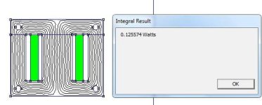
My friend is doing a simulation on a transformer having a diagram like in the first picture. His goal is to find the copper loss resistance(Rcu), and subsequently, the efficiency of the transformer. Then, he use the FEMM to calculate the copper loss (Pcu) in watt first , which is shown by the second picture. After that, he find the true current by using finite element matrix: http://www.femm.info/wiki/mytransformer, and apply the equation Rcu = W/I^2. The simulation is done in the plannar mode.

However, after using this Rcu, the efficiency of his transformer from simulation is exceedingly high (about 95%). But in his practical test, it is only 85-90%.

Is there any flaws in his methodology?

Thank you
BlackMelon
 

Attachments

  • loss_wattjpg.jpg
    loss_wattjpg.jpg
    20.8 KB · Views: 1,374
Back
Top