Field Oriented Control using dsPic33

Alan B said:
Lebowski said:
Alan B said:
Very nice work!

After having done what you have, do you feel the extra speed of the ARM is worthwhile? Would it make the job easier or not?

Looking at my controller etc, the capabilities of the ADC are most important, processor speed comes second. For me an ARM makes no
sence as I don't need the speed and it would need a separate ADC chip...

If the ADC is the most important item then perhaps a separate ADC is indicated. ADCs in micro chips are hardly the epitome of ADC performance!

The ADC's of the 30F / 33F have the capability to sample 4 inputs at the exact same time, something which is crucial to my controller. I don't really
need more bits than the 10 provided, its the simultaneous sampling of analog signals that is hard to find on other chips...
 
Lebowski said:
Looking at my controller etc, the capabilities of the ADC are most important, processor speed comes second.

The higher CPU speed and more Flash and SRAM is allways useful. Especially if the price is comparable to 8bit MCUs or even lower.
I also prefer a clean C code over a assembler mess ;)

For me an ARM makes no sence as I don't need the speed and it would need a separate ADC chip...

What's wrong with a builtin ADCs of the common ARM MCUs?
In addition some of them have additional units very usefull for a motor sensing/driving, like the MB9AFxxxx line from Fujistsu.
 
Alan B said:
Very nice work!

After having done what you have, do you feel the extra speed of the ARM is worthwhile? Would it make the job easier or not?

I haven't done enough work on this project yet to make any serious jugement.

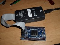
But I did get an ARM Coretex M3 prototyping board from China, and an inexpensive J-link programmer to have a play last year.
The YAGARTO tool chain is freely available including the GCC compiler and the Eclipse IDE is also free.

ARM kit.jpg

It all took a while to learn about and piece together, But after many long hours I was at the stage where I could harness the awesome power of the mighty ARM chip.
I got it to flash an LED and send the characters "hello world" to my computer screen.
After that, I put it away for the summer and haven't got it out since.

The thing about the Microchip stuff is, for me at least, it seems much more intuitive, and there is whole lot of freely available example code that can quickly get you going in the right direction (much of the motor control building blocks are written in Assembler, so will only run on the Microchip products).

I didn't find same the level of support available for the ARM architecture.
I will dig the stuff out again and do more with it one day, but for now I am happy with the Pic dsp.

Burtie
 
Lebowski said:
The bandwidth is not determined solely by the sample rate (20 kHz), but by samplerate and loop coefficients... pity I can't see the code here

Code:
//******** D Control Loop Coefficients *******
#define     DKP        Q15(0.05)
#define     DKI        Q15(0.01)
#define     DKC        Q15(0.99999)
#define     DOUTMAX    Q15(0.99999)

//******** Q Control Loop Coefficients *******
#define     QKP        Q15(0.01)
#define     QKI        Q15(0.005)
#define     QKC        Q15(0.99999)
#define     QOUTMAX    Q15(0.99999)

PI Coefficients --Sorry if this doesn't mean much out of context
 
Burtie said:
But I did get an ARM Coretex M3 prototyping board from China, and an inexpensive J-link programmer to have a play last year.
The YAGARTO tool chain is freely available including the GCC compiler and the Eclipse IDE is also free.

Burtie

Here are a couple of other potential low cost ARM motor control solutions.
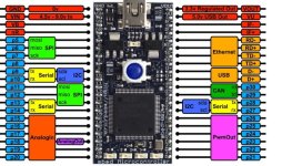
- mbed NXP LPC1768, $51 (AN10898)
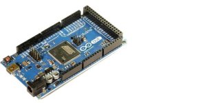
- Arduino DUE, $49

I'm not sure if the free compilers are optimized to the extent that you could do the timing critical stuff required for 3-phase motor control.
 

Attachments

  • mbed.jpg
    mbed.jpg
    74.2 KB · Views: 2,887
  • arduino DUE.jpg
    arduino DUE.jpg
    27.3 KB · Views: 2,887
Burtie said:
Lebowski said:
The bandwidth is not determined solely by the sample rate (20 kHz), but by samplerate and loop coefficients... pity I can't see the code here

Code:
//******** D Control Loop Coefficients *******
#define     DKP        Q15(0.05)
#define     DKI        Q15(0.01)
#define     DKC        Q15(0.99999)
#define     DOUTMAX    Q15(0.99999)

//******** Q Control Loop Coefficients *******
#define     QKP        Q15(0.01)
#define     QKI        Q15(0.005)
#define     QKC        Q15(0.99999)
#define     QOUTMAX    Q15(0.99999)

PI Coefficients --Sorry if this doesn't mean much out of context

if the DKI are the integrator coefficients like in:

output[n] = output[n-1] + DKI * input [n] (simple integrator, the output is the previous output plus the input times DKI)

then the BandWidth is (DKI * f_sample) / (2 * 3.14)

So pretty low I would say (30 to 60 Hz with 20kHz f_sample), good for regulating a long term average, not for following a voltage closely thoughout one e-rpm
 
The DQ transform has effects similar to an FM modulator: It shifts the frequency down by multiplying the signal with the input frequency.

Unlike a radio FM modulator, which has a real-valued input and complex-valued multiplier, the DQ transform has a complex-valued input and complex-valued multiplier. Therefore, you need to consider the transform's effects on a two-sided spectrum that includes "negative" frequencies. The fundamental frequency in the complex alpha-beta domain is positive and shifted down to DC. The fifth harmonic has a negative frequency in alpha-beta, so it gets shifted down to a negative-frequency sixth harmonic. The 7th harmonic has a positive frequency in alpha-beta, so it gets shifted down to a positive-frequency sixth harmonic. And so on and so forth.

The net result is that in FOC (aka DQ-domain control), you don't need much bandwidth at all in order to produce sine-wave output at any frequency. Unsaturated PI control ends up having infinite gain at the fundamental frequency, because of the way it shifts the fundamental frequency to DC. But you still need almost the same amount of bandwidth to control harmonic distortion.
 
So because we dont have a high enough bandwidth in this system to control the harmonics, the alpha-beta components will always be sinusoidal ?
 
Burtie,
I dusted off the old dsPICDEM MCLV development board and hooked it up to a stock wound C80-100 (130kV). I loaded AN1078_dsPIC33FJ32MC204_MCLV (sensorless FOC) onto the MCLV board and fired it up with 24V. The motor oscillates/stutters back and forth and every so often it will spin a few revolutions at low rpm (I will upload a video shortly). I have attached part of the UserParms.h file below to show which parameters I changed (just guessing at the phase resistance and inductance). Also attached is a picture of the phase voltage of the motor when spun with a drill. It's relatively close to a pure sine wave which means FOC should work for this motor, right? I would like to try your modded code with hall sensors at some point. I won't have a power board though anytime soon. In the mean time I will try to get through reading the apnote.
Martin


Code:
#define LOCKTIMEINSEC  0.25		// Initial rotor lock time in seconds
								// Make sure LOCKTIMEINSEC*(1.0/LOOPTIMEINSEC)
								// is less than 65535.
#define OPENLOOPTIMEINSEC 5.0	// Open loop time in seconds. This is the time that
								// will take from stand still to closed loop.
								// Optimized to overcome the brake inertia.
								// (Magtrol AHB-3 brake inertia = 6.89 kg x cm2).
#define INITIALTORQUE	2.0		// Initial Torque demand in Amps.
#define POLEPAIRS      	7       // Number of pole pairs
#define PHASERES		((float).01)	// Phase resistance in Ohms.
#define PHASEIND		((float)0.0001)// Phase inductance in Henrys.
#define NOMINALSPEEDINRPM 2700	// Make sure NOMINALSPEEDINRPM generates a MAXOMEGA < 1.0
								// Use this formula:
								// MAXOMEGA = NOMINALSPEEDINRPM*SPEEDLOOPTIME*POLEPAIRS*2/60
								// If MAXOMEGA > 1.0, reduce NOMINALSPEEDINRPM or execute
								// speed loop faster by reducing SpeedLoopTime.
								// Maximum position of POT will set a reference of 
								// NOMINALSPEEDINRPM.
#define MINSPEEDINRPM	500	// Minimum speed in RPM. Closed loop will operate at this
								// speed. Open loop will transition to closed loop at
								// this minimum speed. Minimum POT position (CCW) will set
								// a speed reference of MINSPEEDINRPM
#define FIELDWEAKSPEEDRPM 4000 	// Make sure FIELDWEAKSPEEDRPM generates a MAXOMEGA < 1.0
								// Use this formula:
								// MAXOMEGA = FIELDWEAKSPEEDRPM*SPEEDLOOPTIME*POLEPAIRS*2/60
								// If MAXOMEGA > 1.0, reduce FIELDWEAKSPEEDRPM or execute
								// speed loop faster by reducing SpeedLoopTime.
								// Maximum position of POT will set a reference of 
								// FIELDWEAKSPEEDRPM.
 
Mauimart my small colossus (80-100 equivalent) is 75kv and 54uH inductance. So if you are 130kv you will have just under 4x less inductance....? Measure it or maybe re-try your settings based on something ~15uH???
 
mauimart said:
Burtie,
I dusted off the old dsPICDEM MCLV development board and hooked it up to a stock wound C80-100 (130kV). I loaded AN1078_dsPIC33FJ32MC204_MCLV (sensorless FOC) onto the MCLV board and fired it up with 24V. The motor oscillates/stutters back and forth and every so often it will spin a few revolutions at low rpm


Yes I had the exact same problems with the standard setup.

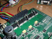
1st problem is the standard power stage will barely pass enough current to start these motors. My solution to this was to shunt the three current sensing resistors with some thin bits of copper wire.

2nd problem is the parameters that control the open loop sensorless startup need much playing with to get to work. I never got the open loop startup routine to work very well, so I replaced it with the close loop hall position sensing.

I also did away with the sensorless closed loop position estimator, so there is no need to enter the inductance or resistance of the motor any more.

Shunt wires on MCLV board.jpg


I will PM you the code changes for the hall sensors.

Burtie
 
Burtie said:
So because we dont have a high enough bandwidth in this system to control the harmonics, the alpha-beta components will always be sinusoidal ?

In the alpha-beta reference frame, the controller's output voltage will always be sinusoidal. But the motor's BEMF may not be. Therefore, the harmonic currents will be purely reactive. The equivalent circuit for each harmonic is the BEMF of the motor in series with its own windings, and it's terminals shorted together.

In the DQ frame, the first harmonic of interest for control is the sixth, since this is where the fifth and seventh of the motor BEMF are transformed.

Note that the controller's line-to-neutral voltage can still have a so-called "zero sequence" componant composed of DC and the triplen harmonics (third, ninth, fifteenth, etc). They can serve to increase the effective line-to-line voltage that the controller can produce. For analysis, you would augment the alpha-beta frame with a gamma term, and DQ with a 0 (numeral zero) term to represent the common mode voltage between the controller's output terminals and it's DC terminals. But since there is no neutral wire between the motor and the controller**, it does not generate any current to the motor and can be controlled open-loop. Effectively, the ABC controller voltage looks like a rounded trapezoid, or flat-topped sine wave, but the current will still be a pure sine wave (plus any BEMF-driven residual distortion as described above).


** Aside from ground. There actually is a parasitic circuit that can return zero-sequence current back to the controller through parasitic winding capacitance, motor bearings etc., but its basically irrelevant for control.
 
Arlo1 said:
Mauimart my small colossus (80-100 equivalent) is 75kv and 54uH inductance. So if you are 130kv you will have just under 4x less inductance....? Measure it or maybe re-try your settings based on something ~15uH???

I changed the inductance parameter to .000015H and am still getting the same result. I will continue to see if I can get the sensorless FOC to work but before I do I must read up a bit more about FOC and try to understand it and the actual code. I can spend hours just tweaking parameters but I think that will be a dead end.

I loaded AN1160 (Sensorless BLDC code) just to make sure that my control board was functioning properly. I get impressively good control with this algorithm, even at low speed (<100rpm). So all seems well with the board. The small FET's (FQB55N10) on the board do seem to have enough guts to get the motor spinning in sensorless mode. At 24V the motor is drawing 3.2A @ 2680 rpm under no load conditions which comes in at roughly 120kV (close to the spec'd 130 kV). See video below for the results.

[youtube]U9pTwCghm0M[/youtube]

I am currently working on getting the external halls configured correctly using AN957 (sensored BLDC control) and once I get that dialed in I will proceed with Burtie's modified code for sensored FOC. Thanks for the code Burtie. Udates to follow...
 
mauimart said:
The small FET's (FQB55N10) on the board do seem to have enough guts to get the motor spinning in sensorless mode. At 24V the motor is drawing 3.2A @ 2680 rpm under no load conditions


You probably have better results with AN1160 (Sensorless BLDC trapezoidal) because it does not use the phase curent monitoring circuitry.

The FOC (AN1078) runs into trouble because it depends on the phase current sensing circuitry, which saturates at about 4.3 amps (hardly enough to spin up the 80-100).
The shunt mod will raise this current limit to something more realistic.
 
I managed to dig out the dyno and connect it up to The FOC setup to see what would happen:


http://www.youtube.com/watch?v=GnusUMRFWq8&feature=youtu.be

[youtube]GnusUMRFWq8[/youtube]


Burtie
 
Burtie whats involved in getting the microchip real time feedback up and running on the computer screen?? Lebowski is this something we can do??
 
Arlo1 said:
Burtie whats involved in getting the microchip real time feedback up and running on the computer screen?? Lebowski is this something we can do??
The controller IC has this feature, i think Nieles got it to work. The easiest is to use Labview but you would need a linux PC to run the free 6.1 labview version that I use.
 
Arlo1 said:
Burtie whats involved in getting the microchip real time feedback up and running on the computer screen??

Here is the userguide for the RTDM feature.
http://ww1.microchip.com/downloads/en/DeviceDoc/70567A.pdf

Trouble is that the hooks to read the variables are added to the application at compile time, so you need the source code.
 
Burtie,

It spins! I added the shunt wires across the shunt resistors, compiled your code, flashed it and we now have FOC. It's quiet and smooth. Minimum rpm is about 77rpm and it tops off at 1740rpm @ 24V, 2.2A. Some things I noticed when comparing to AN1160 and AN957. Max speed for AN1160 is 2680rpm @ 24V, 3.2A. Max speed for AN957 is 3060rpm @ 24V, 3.5A. Any idea what's limiting the FOC code to 1700rpm. My external hall setup is not the best and I think the timing that established using AN957 is a few degrees advanced. I also noticed that when the push button is in the off position, all three low-side FET gates are commanded on which brakes the motor. Anyway looks like I have to get some sort of power board running again. I'm looking at doing a 12 FET version of this one http://endless-sphere.com/forums/viewtopic.php?f=30&t=23350&p=423626#p423626 based on Jeremy's Simple BLDC Controller). I would like to add some 200A Allegro Hall current sensors to monitor phase current instead of using shunts. Do you think those will provide the necessary bandwidth to work with your code?

[youtube]J2gDgK7OeYc[/youtube]
 
mauimart said:
Burtie,

It spins! I added the shunt wires across the shunt resistors, compiled your code, flashed it and we now have FOC. It's quiet and smooth. Minimum rpm is about 77rpm and it tops off at 1740rpm @ 24V, 2.2A. Some things I noticed when comparing to AN1160 and AN957. Max speed for AN1160 is 2680rpm @ 24V, 3.2A. Max speed for AN957 is 3060rpm @ 24V, 3.5A. Any idea what's limiting the FOC code to 1700rpm. My external hall setup is not the best and I think the timing that established using AN957 is a few degrees advanced.
Good news.

FOC puts the amps into the motor at the best possible time to produce torque but that maybe not the best possible time to get Hi rpm. Hmmm I wonder if it matter when you are riding it. I meen you want the amps fed into the motor to make the most torque per amp thats what FOC does but for top speed it might still be the best with FOC with out the highest unloaded speed.

Otherwise is the throttle current based or speed based??
 
I forgot to mention but also noticed that when I put a small load on the motor the speed reduces and input current remains the relatively constant. When I load the motor while driven with the other algorithms the input current will increase to keep the speed constant.
 
That means you have a current based throttle.
 
mauimart said:
I forgot to mention but also noticed that when I put a small load on the motor the speed reduces and input current remains the relatively constant. When I load the motor while driven with the other algorithms the input current will increase to keep the speed constant.

You can play with the PI constants for the speed controller in Userparams.h to modify this behaviour. Try increasing the integral term a bit to reduce the long term speed error.
You may also increase the proportional term to tighten the speed control a bit, beware though, increasing things too much will make it unstable.

Also, play with the value of PhaseAdj variable ( in sensors.c ) currently set to 11000. This adds an offset to the phase signal from the hall sensors, so you can use it to alter the static timing reference. (65535 is equivalent to 360 e degrees, so about 182 per e degree)


There is still much work to do to get this useable, but I am not able look at it until the weekend. We will get there bit by bit :)
 
Nice results! How exactly are the halls being used in the FOC algorithm?

In FOC control there are two currents in the rotating frame, one produces torque (IsubQ) while the other (IsubD) produces flux, or field weakening. Normally the flux field current is set to zero in a permanent magnet motor. If you want to increase top speed some field weakening (flux opposing the permanent magnet flux) will raise the Kv of the motor and produce increased speed at the loss of some torque and efficiency.
 
Back
Top