amberwolf said:The throttle itself always varies it's voltage.wobble said:So the throttle sohuld vary voltage and not current?
What it causes the controller to vary at the motor, for a brushed system, is the width of the voltage pulse to the motor. The voltage pulse is always battery voltage. How long it applies that voltage determines the current draw of the motor. The current is also in pulses, becuase the voltage is in pulses, and also changes. So the controller varies the average current by varying the average voltage by varying the width of full-battery-voltage pulses. Because of the motor inductance and resistance, it may not look like "squarewave" pulses, but that's how brushed controllers work.
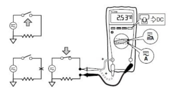
Unless you use an oscilloscope you can't see this occuring, and the only "valid" multimeter / ampmeter / voltmeter measurement you can make of what the motor is doing is at the battery input to the controller, not at the motor output from the controller.
If it's always 4.4v, then it cannot vary the speed of the motor.wobble said:amberwolf said:But what is the actual throttle signal voltage, at the controller's signal input?
If that dosent' vary, then neither will the controller output.
The throttle was about 4.4V and it is able to vary the speed of the motor. The seller of the controller had paired it with the throttle and sold the two together in a package deal.
The throttle voltage must vary with throttle rotation.
If it is able to vary the speed of the motor, then the voltage at the motor, and the current draw from the battery, will also vary.
What is the actual throttle signal voltage, at the controller's signal input, when at zero rotation?
What is the actual throttle signal voltage, at the controller's signal input, when at maximum rotation?
What is the motor's current draw when directly connected to the battery?
I've tried my best to answer your questions:
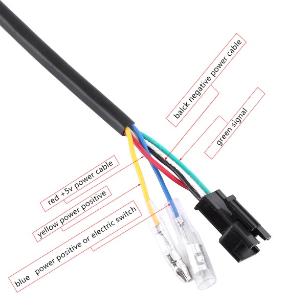
I measured the throttle voltage between two of the wires which go from the throttle to the controller
1. The throttle voltage at zero rotation is 4.4V
2. The throttle voltage at max rotation is 4.4V
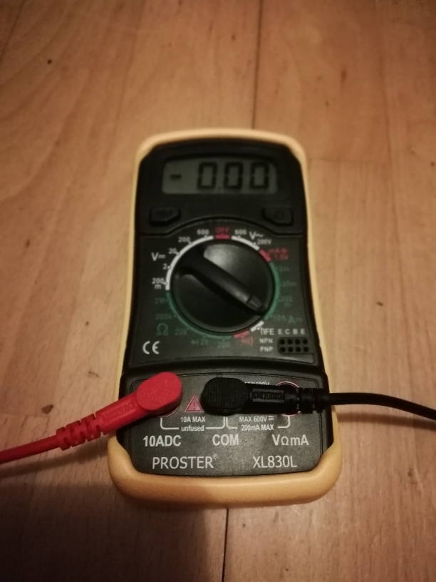
3. The motor draws more current that i can read so >19A when connected directly to the battery
I'm so confused because i thought the controller would be regulating the voltage and current, and also that the motor would draw less current from the battery when directly connected.
")