Fisher and Paykel motors

here ya go
below diy controller to run fp, very ineffecient method, but nice to watch leds flash on off as hall sensors fire,
circuit deisgned by warwick smith numurkah secondary school australia
fp1.jpg
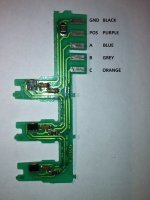
parallel connection diagram
fp 2.jpg
shows pos/neg pins, other three are output voltages of the halls
 
@whatever: Thanks so much for the additional info! I really appreciate that! Those would be very beneficial for my EV project. :D Just a quick question, where could I get that PWM board?

Nicko
 
see top diagram: pwm board from dick smith electronics, catalogue number given but diagram is very old ( maybe 10years ) so cat no. may have changed
but!!!
I would use an ebike controller such as from bmsbattery , above simple controller works but not efficient, also neomagnets have to be used, hopeless with ceramic magnets, its good educational tool how to run 3 phase fp motor but for ev project you really need to use 12fet or higher ebike controller
 
whatever said:
see top diagram: pwm board from dick smith electronics, catalogue number given but diagram is very old ( maybe 10years ) so cat no. may have changed
but!!!
I would use an ebike controller such as from bmsbattery , above simple controller works but not efficient, also neomagnets have to be used, hopeless with ceramic magnets, its good educational tool how to run 3 phase fp motor but for ev project you really need to use 12fet or higher ebike controller

I've had a nice chat with Edward Lyen lately and he seems to be a really good source of information regarding brushless motor controllers. He also provided a user-friendly procedure on how to use the controller on his website. Easy to understand too! As of now, I'm counting on his Infineon IRFB4110 12-FET Controller, which he claims to be similar to the one used by F&P guy. What really intrigues me about it is the compatibility to use it with Cycle Analyst (formerly called DrainBrain) so that you could easily monitor the data of your motor.

However, I'm having second thoughts about Kelly Controls' KBS72051 (http://kellycontroller.com/kbs7205120a24-72v-mini-brushless-dc-controller-p-505.html) lately. It's a little bit cheaper than Lyen's. But enooob guy stated in the previous page that Kelly controller doesn't like the hall sensors circuit made by Fisher and Paykel, making it inconvenient for me to buy, align, and wedge new sensors between the stator teeth. I'm just becoming more uncertain to buy and use it.

What do you think?
 
I highly recommend buying from Lyen, he is a solid guy. I have had his 12 Fet, 18 Fet, and 24 Fet controllers. Still using his 12 Fet and a 24 Fet controller.

His 12 Fet controller is a very good controller. I have used it on a geared BMC, X5, and 9C. People even use it on Cyclone motors.

The good thing about the Lyen controller, as you point out, is that you can get it so your Cycle Analyst (Direct plugin) plugs straight in. You can also get Lyen to fit it with a programming cable so you can program it. His response time, packaging, and service is top shelf.
 
Philistine said:
I highly recommend buying from Lyen, he is a solid guy. I have had his 12 Fet, 18 Fet, and 24 Fet controllers. Still using his 12 Fet and a 24 Fet controller.

His 12 Fet controller is a very good controller. I have used it on a geared BMC, X5, and 9C. People even use it on Cyclone motors.

The good thing about the Lyen controller, as you point out, is that you can get it so your Cycle Analyst (Direct plugin) plugs straight in. You can also get Lyen to fit it with a programming cable so you can program it. His response time, packaging, and service is top shelf.

It really inspires how Lyen responds to his clients' needs in a very professional way (knowledgeable in his stuff, fast reply in Emails, reliable to transact with). Just a little OT, how much did it cost you for the Cycle Analyst? Kindly PM me the price in USD. Thanks! :)
 
you could replace the hall sensors in the fp board, the fp board comes out very easily, very easy to work on it,
its not really the circuit that is a problem ( they are all the same pretty much) its the output of the hall sensors they use which might cause some issues, ebike hall sensors are physically a bit different to those used in the fp motors, but there output will work with any ebike controller pretty much. not a big job to change hall sensors, I think a worthwhile exercise if your not very familiar with ebike things.
 
Ei guys, I need help ASAP. I and my friends tested our F&P motor with Lyen's 12 FET controller (5k pot as throttle control) last weekend. Unfortunately, all 36 combinations exhibited a single movement/step (as I rotate the pot) and then came to a stop. Just a little bit of info, we rewired the windings from series to parallel (same as what F&P guy did - all ends of each phase are connected as common point in wye connection), & the sensors we used are the ones provided by F&P motor. I am certain that the controller isn't the problem. Could it be the windings? What do you think? :?

Nicko
 
it may be the hall sensors are the issue, I'm not sure what the guy in melbourne (fp guy) used, if any doubt change them to ebike halls, dont use ones from jaycar/dicksmith, hall sensors have different output voltages/millamps, need to use correct ones from ebike dealer ( I've tried!!!)
you can connect them 60 or 120 degree
60degree: all facing upwards
120degree: middle sensor upside down
make sure put them in exact same position relative to the stator if you change them, position is quite critical
 
I had a chat with Matt Lyons this morning and he also suspects that the sensors were faulty as he had experienced the same issue in the past. Also, I noticed that only two hall sensors displayed a voltage relative to ground while the other one is approximately zero or nothing at all. I'll try to replace the sensors this weekend and will tell you the outcome. One more thing, if ever my new F&P sensors has the same issue again, could I use this type of hall sensor for my hub motor? Do I wire it as is? Does it need additional circuit devices (resistors, capacitors, etc.) similar to F&P sensors? It's the only thing I could find here locally.

Nicko
 
I've got 44E (712) and 3144 ( 712) , both are for ebike controllers, I can sell you some of those if you like, I'm in australia.
I'm not sure if the one on the pdf you posted are suitable or not
 
We tested our motor with 12 out of 36 possible combinations this afternoon. All of these 12 combinations have second phase wire from motor matched with second phase wire of the Lyen controller (the green one). Sad to say, some exhibited the same issue while others exhibited an oscillation like it wiggles in one spot. Video demo here. It's kind of weird but it has gained little improvements over our last sensor. First sensor has an output of around 5V, second around 2V, and third around 1V. Is that supposed to behave that way? Also, we checked the resistance per phase and ohmmeter reads an average reading of 0.57 ohm. Is that ok for a 60S stator wired in parallel (60P)? A couple of questions also,

1) Regarding the measurement of resistance per phase, we did it by measuring line to line (i.e., A-B, B-C, & A-B). Is this correct?
2) Should we connect the common point to ground?
3) Would it be advisable to control it by a sensorless controller to avoid issues regarding the sensors?
4) On another thought, how if we just detach the motor of a SmartDrive washing machine, install it inside the rotor, and use the control of the washing machine? Would that be fine doing as well?
 
Ei guys! I finally got it to work! Thanks to our adviser who suggested replacing the factory sensors to e-bike halls. The whole motor is from Fisher and Paykel including stator and rotor. Stator is originally wound as 60S and rewired into parallel (60P) to increase its current carrying capacity from 1.5A to 20A. Rotor is made of aluminum but the steel liner is retained along with the stock ferrite magnets from Fisher and Paykel. Rotor spline is removed.

Before, we used the stock sensors from F&P but we noticed the same behavior for all the 36 combinations like this. Until the other day when my adviser noticed that the output of the sensors is at mV range, he then decided for us to replace it with e-bike hall sensors. Luckily, he was right! Video demo of the motor with new hall-effect sensors can be viewed here.
In this video, the motor is actually running at ~45VDC and about half of the maximum speed. Controller used is Lyen's 12 FET controller (EC-124110-LYEN EDITION).

Thanks to all those who supported my project especially to Matt Lyons, fechter, whatever, and Edward Lyen! You guys made it possible!
 
well done! congrats, please keep us updated with your experiments as you progress, going to neo mags will make a big difference too ( stronger mags will make rpm lower and torque higher)
 
whatever said:
well done! congrats, please keep us updated with your experiments as you progress, going to neo mags will make a big difference too ( stronger mags will make rpm lower and torque higher)

Gee thanks! I bet neo mags would really kick ass over stock ferrite magnets. We tried however using N51 magnets a year ago but we noticed that due to strong attraction of neo magnets to the iron core, the motor couldn't spin freely by hand. Is that normal? Would the motor still run in that case?
 
if your neos were touching the iron core anywhere that would lock it up, need to have a tiny gap between the coil core and the magnet faces. Also fp motors do have cogging but this can be reduced by filing off the edges of the iron core where they exit the coil ( thats been discussed for many years)
nice link
one note on fp motor controllers: it may well be possible to run an fp motor ( as a washing machine ) on a low voltage source,
by changing the fets, never tried it, but pretty sure would make a great low volt dc washing machine
 
Actually, we provided a 1mm air gap between the neo mags and iron core.. Still the same result - the motor couldn't spin by hand... Anyway, we haven't considered decogging the stator as we haven't had enough time doing it. But we're pretty sure it would increase the motor efficiency by a significant figure. Here are two other tips that could reduce cogging of FP motor - http://www.thebackshed.com/windmill/articles/decoggingFP.asp

Another thing I'm concerned about is the power supply. What type are you using? Battery or bench type? We wanted to reach the potential of our motor but running it at 48V left us with a maximum efficiency of 26% under maximum speed of 770rpm with load. Our Lyen controller could accept up to 88V and deliver a maximum output power of 3500W. Any suggestions how we could obtain that amount of power? BTW, we're currently using 2 Cosel P600E-24 connected in series, which gives us a 48V, 1300W of power.
 
it looks like your cogging is a very big issue, it was maybe 10years or more ago when I was messing with fp motors.
ebikes in china were just beginning and there weren't controllers available, hence I built my own, my efficiency was also very low, amp draw was high, but it was free spinning ( i was using the ceramic mags and just rewired in parallel)
I ran on 36v from memory. My power source at the time was a briggs and stratton ( 2hp??) engine running a old tape motor as a gennie, which charged up two lots of sla battery strings ( 36v 18ahr each).
It was a three wheeler with no fairing. I did have alot of headaches with the home built controller ( blowing fets mainly).
You may or may not be aware of a guy selling a123 cells 20ahr pouches on ebay ( from china) , they are seconds but from what I hear they are quite good capacity. You can pick them up via china very cheaply if you have chinese contacts ( about half price of what the ebay guy sells them, exact same cells, but you need a chinese contact to do that, if you want any help with that I can assist privately).

On the cogging: do you know the dr eck motor used in ultralights? ( german), its almost identical to the fp motor ( no coincidence I think), the difference being his iron fingers ( coil laminations) are shorter than the fp, that might be how he has reduced cogging ( but I haven't found any really detailed info on the motor to confirm any other changes to reduce cogging). You should be able to get up near 85% efficiency if you can overcome the cogging issue, there may be some other factors contributing ( such as winding resistance etc) but thats a bit beyond my skill.

If shortening the iron fingers is a way to reduce cogging, then it would be possible to glue neos over the old ceramics and reduce diameter of motor by shortening fingers, but would require rewinding the poles, it might be hard to glue directly onto the old ceramics also.
It might be worth checking with mathew in melbourne ( username: f&p ) on his cogging. I've never tried to put neos into an fp motor, but its something I need to do in future for a project I'm working on. So i'm very interested in your work.
 
i think twisting the stators will be easiest way to reduce your cogging, maybe no need to file off the edges.
 
Gee thanks for the info! :D Lots of sources indeed! I and my thesis mates are still on the process of analyzing the performance of our FP motor. And yes you're right! Cogging is really a big factor in our prototype. The simplest way to do is either file off the edges or skew the stator slots. We'll probably recommend it for future work as we haven't got enough time to do it. As of now, we have achieved a 30% efficiency at 48V controller supply, drawing around 17A(rms) in controller output. The motor is under load by applying a mechanical brake. Is that reasonable enough? Will increasing the power supply to 88V (max of the motor controller) would further increase efficiency?
 
+1 Subscribed.

My dad is retired from 20 years of Washing machine repairs but still has lots of parts. I have four in my workshop, 0.6mm up to 1mm, and the new generation decogged magnets from the factory.

Let me know if you need parts or pics...
 
Hello everyone
I stumbled across this forum and it is a very interesting source of information.
Right now I am trying to run a Fisher Paykel motor from a brushless DC industrial drive.
It supplies 5V for the halls and has 3 connections for the outputs.
I am using the standard hall board for the motor but I cant measure any output when I rotate the motor by hand with power applied to the halls.
The motor has no motion and locks.
I've tried swapping the hall sensor board and same result.
I am getting 3 different voltages on the hall outputs 5V- 1V- 2V but they dont change.
Does anyone have any suggestions which could help me get some outputs to the controller from these boards.
The drive also has a jumper switch for 60 degree or 120 degree sensor phasing but I dont know which the FP board would be.
I have seen an led tester for the halls which runs on a 9V battery so I assume they will work on that but if anyone knows what voltage range to use I would appreciate it.
Or perhaps what I might need to do to modify the halls.
Thanks
 
I'm sure the picture in the post on the previous page was wrong regarding the FP Hall Board wiring.
I have the motor running now.
But too much current for some reason and it's heating the windings too much so I'm off to investigate.
The picture attached is the correct wiring.
 

Attachments

  • FP Hall Sensor (602x800).jpg
    FP Hall Sensor (602x800).jpg
    85.1 KB · Views: 4,971
what voltage are you running?
have you made any mods to the fp wiring?
they are wound to run on a certain voltage ( which I cant remember off top of my head) it was pretty high
rewinding them into parallel connection they make a good low voltage motor, but not modded they need a pretty high voltage
as a generator just turning by hand you can easily get up near 100v output if unmodded
 
Back
Top