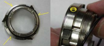
Fitting freewheels to splined freehub drivers

Pics will help a bunch. :roll: I'm still trying to get my head around how you are going to do this, and what sort of tools/machines are required. I'm going to have to get out the 22T ENO I have, and compare it to the hub. Is it that only the removal tool end of the ENO, where it narrows down a bit, is the part that has the splines? I get that you need to mill off the threads, so that portion will fit over the outer spline diameter, but I'm confused about what is it that you are cutting down to 32.5mm? Oh, wait, is that what will end up being the inner diameter of the spline "teeth"? That would give .02mm clearance, right?

You guys are making my head hurt again... :? :mrgreen:
 
file.php


file.php


or read the whole thread ....http://endless-sphere.com/forums/viewtopic.php?f=28&t=12449&start=210


Just wondering if on the motor drive freewheel, if there is any advantage to broach a one way bearing instead of a freewheel sprocket ??

still use the freewheel sprocket for the second freewheel to the pedals
 
jmygann said:
Just wondering if on the motor drive freewheel, if there is any advantage to broach a one way bearing instead of a freewheel sprocket ??
It's quieter when you're pedalling without the motor... Plenty of scope for reducing the spring strength in the ENO units, though.....

There's no need to broach the one-way bearing but you'd need to make something like the go-kart sprocket hub, for it - or bond onto it, which is what I did.
 
well you could make what is called a "slotting attachment" or Keyway attachment. this is a manual lever operated single tooth broach thing.

s-img_4685.jpg s-img4714.jpg
s-img_4636.jpg s-img_4669.jpg

the slotting attachment just pushes the single tooth cutter through the part. you can take off .001 or .002 each time you pull the handle. the cutting tooth is highlighted by the arrows and circle.

of course if you just put the cutter in the tool post you could move the cutter back and forth using the logitudinal travel of the lathe and adjust the depth of cut using the cross slide. same thing. just less fancy.

when you finish one slot you just manually rotate (index) the chuck to where the next slot will be cut.

rick
 
That is a nice little jig...

The long arm reminds me of a metal spinning lathe.

Miles,
Did you bond a splined reducer inside of the 35mm CSK oneway?
 
12p3phPMDC said:
Miles,
Did you bond a splined reducer inside of the 35mm CSK oneway?
No, I bonded my adapter to the outside of it...

I used the same trick as before, with the splined sprocket, to lock the inside to the freehub driver.
 
Luke,

Wouldn't it be much quieter to put a one way bearing on the pedal cog since you won't ever be pedalling except when you see a cop? :wink:

I think he is busy filing, I bet both these guys will have some sore muscles tomorrow. :lol:
 
bonded meaning ? epoxy ? or clamped like randy ?


Miles said:
12p3phPMDC said:
Miles,
Did you bond a splined reducer inside of the 35mm CSK oneway?
No, I bonded my adapter to the outside of it...

I used the same trick as before, with the splined sprocket, to lock the inside to the freehub driver.
 
come on Miles and Luke - you can do it guys!!!!!!!!!!!!!!! :D :D :D

D
 
Miles said:
Thanks for the pics, Rick. That's a nice little jig.

Yes, thanks Rick, that helps a bit, but I'm still trying to understand how that works. You said you take .001-.002" off each time, but I assume the tool needs to be moved outward another .001-.002", but how is that done?

-- Gary
 
Gary,
In order to move that small an increment you would definately need a lathe and mount the jig on the same mounting plate as the cut tools so that you could wheel the jig in or out incrementally for each pass. So I think for most here the hand filing method should be the only option. At least until we find a machine shop willing to do a run of 10-20 pieces for a decent price. But I'm no expert.
 
GGoodrum said:
Miles said:
Thanks for the pics, Rick. That's a nice little jig.

Yes, thanks Rick, that helps a bit, but I'm still trying to understand how that works. You said you take .001-.002" off each time, but I assume the tool needs to be moved outward another .001-.002", but how is that done?

-- Gary

gary the tool is mounted to the cross slide of the lathe where the toolpost would nornaly be mounted. so you can adust the depth of the cut by moving the slide closer and father out.

the lever arm stokes the cutting tool into and out of the hole. in the photo it is being used to cut a keyway in the gear. the lathe is only used to hold all of the things in the right places. it is not being used as a lathe at all.

rick
 
http://en.wikipedia.org/wiki/Broaching_%28metalworking%29

team358.org/files/mechanical/Broaching.pdf
 
If the ENO "neck" seems insufficient for the load, perhaps the modded driver could also have grub screws installed? It appears to have enough material at the base.

It would mean assembling the ENO in-situ, but that should be a minor annoyance.
 

Attachments

  • ENOgrubs1.jpg
    ENOgrubs1.jpg
    32.1 KB · Views: 3,274
I'm totally not following you Tyler.


Packages came today, and I'm getting started in the destruction of perfectly good freewheels :) :twisted:
 
Maybe I'm off mark... but if I understand correctly, the ID of threaded section of the ENO ain't much gripping anything; just the 'neck' (on the outboard side) where you are cutting the internal splines is torquing on the freehub body. If you want more contact on the freehub body, the grub screws could give you some purchase on the inboard side. (?)
 
The all the working stress loading of the inner freewheel is carried by a generously sized sealed ball bearing. The aluminum part just has 2 thin threads around it to hold the inner body from sliding out of the outer portion. However, this seems more than adquate IMO, as it should carry no load on that axis if properly setup with decent chain angles. Even a little snap-ring clip seems it would be equally adquate as the 2 threads to retain the little aluminum part. It would be possible to mount some grub screws to retain the aluminum part from turning out, but I really wouldn't see the purpose, as it's not really a loaded part.

If I'm too pinched for space to fit two on a 9spd cassette, I'm planning to mill off that entire setup with the aluminum retaining ring, and simply let the contact with the next freewheel on the hub serve as the support to control the position of the outer race.

I was planning to try and finish one up tonight at work, but I'm down to the cutting the splines part of the job, and I realized that I only own a single rear bicycle hub, and it's currently employed in use on my E-bike. When I get home from work, I will disassemble the rear wheel of my bike to give me some splines to use as a tester so I will know when I've got it :)

BTW- These ENO freewheels are heavy! I'm glad it's steel for the torque handling needs, and I'm glad it's steel because working with Ti is awful, but it sure seems like a lot of weight in a little part.
 
OHHHHHHHHHHH! Re-re Luke might have finally just understood what you were after Tyler, and yes, it seems like a fine idea if the splines alone aren't up to the task.

You mean to slide the inner race over, drill it deep enough to put some dents into the splined 9spd cassette reciever, tap the holes in the inner hub portion, and run them down into the cassette driver, then assemble the fixed freewheel onto the inner portion. I think it could add a bit of torque holding perhaps. I'm pretty in love with splines ability to hold torque, and I think they will do just fine.


Sorry for being so dense and not understanding what you were saying! lol

On the topic of spline torque handling, I had a fantastic race last sunday. Supercharged big block trailered drag car VS Luke's daily driver 40mpg civic. :) Single eliminations heads-up racing, so you get no second chances here. When the lights drop, I absolutely tree the piss out of this clown, who starts lifting a tire, gets scared and lets out of it, hits it again, spins the tires, and by that time, Luke's rocket civic from hell is half way down the track all ready, and all his HP and torque can't save him :) There is so much nitrous hitting my engine at the moment I launch, sounds like an air-cannon shooting. lol Splines of a smaller diameter of the 9spd hubs are able to hold 1,000hp and be reliable. Even though it's aluminum rather than 300m steel, I think they will be just fine. :) Enjoy the video :)
[youtube]amuXF6gJQRw[/youtube]
 
There's certainly enough engagement between the splined "neck" and the freehub driver. The neck section overlaps the stepped part of the inner so, although there's a substantial shear force across it at that point, the inner itself should be ok, too. We'll see....

Using the freewheel ratchet mechanism for the angular registration of the splines works a treat. Hold the assembled freewheel by the outer - rotate through four clicks of the mechanism for each slot position and tape across the face to prevent accidental movement while filing :)
 
Have you got one done yet my friend? I'm so excited to work on mine, I almost want to leave work, go take my wheel off, come back to work, and see what damage I can cause. :)
 
liveforphysics said:
You mean to slide the inner race over, drill it deep enough to put some dents into the splined 9spd cassette reciever, tap the holes in the inner hub portion, and run them down into the cassette driver, then assemble the fixed freewheel onto the inner portion.
Yep.

Another way, would be to cut keyways instead of grub-screws, then install keys that engage the freehub splines. You could then slide-on the finished unit; but you might need Rick's shaper to cut keyways. (A moot point, if the handmade splines are sufficient.)

Luke, you could stop at the LBS on the way home and pick up a spare freehub body... you might want one, uh... just in case you break the only one you have.
 
Here's my set-up for guided filing. The nut is removed from the tool slide to allow it to be move back and forth freely. The cross slide is fixed with the file parallel to the bottom of the spline groove. The toolpost screw is loosened enough to allow pressure to be applied to the work, using the bar on the opposite side of the toolpost to the file.
 

Attachments

  • Spline-set-up.jpg
    Spline-set-up.jpg
    78.8 KB · Views: 3,499
Back
Top