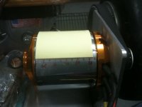
Hopefully this will help someone spec & locate hall effect sensors. I decided to do this after seeing where bigmoose did something similar for the 80mm motor. I'm not sure I understand what the +10º & +20º plots he made are for. If someone wants something like that please let me know & I can probably do it. These are just the readings along the strongest part of one magnet.
45mm ± 10mm from the mount face looks good. Some of the other magnets (not plotted) had anomalous readings at the edges (maybe from the screws), so 45mm ±5mm would be safer. The radial distance would depend on the sensitivity of the HE sensor. The other version of this motor, 6374-200, is probably the same except 1 cm longer. So the ideal spot for it would be 45mm ± 10 to 15mm. I took readings with the probe flush against the can, & used a stack of post-it's to get the spacing for the other readings.
I haven't added the Hall's yet. I'm not sure exactly how to arrange them. I suspect that there should be two on at any given time & one sensor should trip on the instant another switches off. I plan to check a sensored motor I have on the scope. When I add Halls to the new motor, I'll adjust the angle to get the timing & the radial distance to match whatever pattern the sensored motor has.
I can't wait to get the sensors on the skateboard motor. Right now it cuts out so much on acceleration that I'm worried about getting hit by a car when crossing streets. Hopefully when sensored the acceleration will feel like getting a rug pulled out from under me.
edit: I don't know why the graph doesn't load automatically like the photos do, & it says "not downloaded yet" even though at least one person (me) has downloaded it. If you can't access the file "Flux Map of 6364-280.jpg" listed below, let me know & I'll figure out how to repost it or send it to you.
View attachment 2
View attachment 1


