Friction Drive DIY - solar charged

Solar Motion

10 mW
Joined
Nov 23, 2009
Messages
21
First post here, so need to start off with many humble thanks. Spent the better part of 30 hours reading posts, looking at kits, and researching components. As an engineer, I found Endless Sphere most logical and thoughtful. Kept coming back to dig further gaining great ideas along the way. That information gave me the tools to build my own friction drive set up.

The motor is the 450W 24V Currie being sold at allelectronics for $25 (no sproket). Batteries are CSB EVX 12ah. The motor drive shaft connects to a "drill arbor" that costs $7 and is very heavy duty. That holds a 3" rubber caster wheel and rests in a 1/2" bore ball bearing "pillow block" for $8. Motor mount hardware, brackets, mending plates are all from the local hardware store. It's quite solid IMO. This setup does 18mph for 10miles. 25 pounds added to the bike. Replenishing the bike batteries from a bank of 6V deep cycle wet cells charged from the sun. Just finished the bike over the weekend and taking it everywhere. Including trailering my daughter to and from school. Still tinkering, so any feedback or recommendation would be appreciated.

Drive.jpg


Drive2.jpg


Batteries.jpg


MotorWires.jpg
 
Dear Solar Motion, excellenT build! I think everyone should have at least two bikes, and if someone really depends on an electric commuter, 3 bikes with 2 being electric.

The friction drive has several benefits in my view. It can be VERY affordable for a beginner, and as a non-hub, its easy to add active cooling.

Another benefit is for an enthusiast who lives in a bad neigborhood. You can use a cheap used thrift-store beater-bike to get to work/college (no major concern if its stolen once a year). The drive-unit can be made to easily attach/detach so it can be stored inside work/class. If you live in an upper apartment of a high apartment building, the cheap bike can be locked up downstairs and the drive unit carried up (for security, and also charging indoors).

The motor you selected is a very affordable and well-proven unit, and, for someone who wants an ultra-light drive (for easier carrying, or for a light road-bike) the drive can be easily upgraded to a very small RC motor. Thank you for posting this great example.

I have read that a small benefit to traction can be achieved by giving the drive-wheel a "waisted" shape, like a ships capstan. That way it has a more even pressure applied across the rounded tire tread cross-section. I have even contemplated a motor driving one wheel, and adding a second wheel driven by the first wheel. This is because a frequently stated concern has been slippage during wet conditions.

capstan_drum.gif
 
WOW, thats gotta be the cheapest drive out there, besides all you cerbside creepers and CL low ballers. Nice job man, AND its a ZEV cuz you charge from the sun!! Brilliant!! Every friction drive quiets the flamers and reinforces how easy and attainable a DIY friction drive can be. Maybe try posting this in the Photos and Videos section along with a full bike shot. Some efficiency numbers would be coo :p
 
Excellent build, Solar Motion. Welcome to the Sphere. Could you post a detailed parts list (I know you nearly did it at the top) as I'm sure there are members who would want to just copy your work straight away? Thanks.
 
spinningmagnets said:
I have read that a small benefit to traction can be achieved by giving the drive-wheel a "waisted" shape, like a ships capstan. That way it has a more even pressure applied across the rounded tire tread cross-section. I have even contemplated a motor driving one wheel, and adding a second wheel driven by the first wheel. This is because a frequently stated concern has been slippage during wet conditions.

spinningmagnets, thanks for the vote of approval. Have enjoyed your contributions to this site. Could not agree more regarding the relationship between contact surface area, pressure, and slippage. Was playing with one of these http://www.attwoodmarine.com/store/category/trailering/bow-stops-rollers (bottom right, although there are several other shapes) during the initial assembly stage. 1/2" bore, good shape and contact, durable, and spun true. However at 3" wide, could not center it on the tire with my current motor mount dimensions. Still planning on making it work, perhaps on the second build like you suggested.

Also appreciate the link to your on-going solar panel/charging thread. Planning to get involved there and contribute to the discussion if possible.
 
paultrafalgar said:
Excellent build, Solar Motion. Welcome to the Sphere. Could you post a detailed parts list (I know you nearly did it at the top) as I'm sure there are members who would want to just copy your work straight away? Thanks.

Glad to provide more details. At the beginning, considered many kits concerned a DIY build would be unsuccessful or more costly and under perform. Or that purchased parts would go unused or broken during the process. After pricing out kits with and w/o batteries then pricing out the components, the learnings found here started me ordering parts from multiple vendors. Here's a few that were used:

Motor - 450W 24V installed right side (running reverse polarity)
http://www.allelectronics.com/make-a-store/item/DCM-1501/24VDC-450W-MOTOR-D-SHAFT/1.html

Arbor - comes in 1/2", 3/8", 5/8" diameters to fit motor shaft. Drilled thru arbor and installed a shear pin thru motor shaft and arbor.
http://www.drillspot.com/products/97448/Dayton_3ZN03_Fractional_HP_Motor_Shaft_Arbor

Pillow Block - their ebay store sells for $8. Very heavy duty. 5" wide!
http://www.sasbearings.com/product_info.php?products_id=43

Battery/Controller Case - had HF coupon cost $10
http://www.harborfreight.com/cpi/ctaf/displayitem.taf?Itemnumber=36870

Hardware - all came from Home Depot. Used 1/4" bolts of various lenghts. Needed to drill six additional holes for everything to line up.
http://www.hardwareandtools.com/invt/033923485258
http://www.hardwareandtools.com/invt/6462568
http://www.hardwareandtools.com/invt/6712103

The 24V controller (500W) and twist throttle were from TNC Scooter.

Total cost including batteries http://www.zbattery.com/CSB-EVX1220F2-SLA-Battery?sc=2&category=60822 was less than $200.

Can provide more details if anyone needs them. Happy to do so, just let me know.
 
Thank you very much for posting the components for the drive set-up! I intend to do a roller drive for a future build and what you did is perfect.
Mike
 
Thanks for the positive comments! Have 200+ miles on it so far and still thrilled when that brushed motor whine kicks in. Made a few minor adjustments before the really cold weather rolled in. Will take a few photos and post an update. Was getting a "safe" 6 miles out of the original 12ah batteries. Upgrated to twin Ritar EV 22ah sla's (just can't let go of lead acid yet) and have a Turnigy meter sitting here that needs implementation. Hoping for some warmer weather real soon.
 
Thank you, just what I was thinking about and wondering if I could do it. You sure did a nice job of explaining it to us. I want to give it a try using your design and ideas. Just getting started with the electric bicycle idea and have learned a lot from this forum. I think you have just finalized the place I want to start.

Best Regards

Bill Snow
 
Looks good. Does it freewheel when pedalling? About the shaft support: I assume its a bushing with the grease fitting?
 
Solar- I think you need to get your controller out of the box on the back, (I assume that is the silver thing I see) to where it can cool during use.
Very nice job,
Mike
 
D-Man said:
Looks good. Does it freewheel when pedalling? About the shaft support: I assume its a bushing with the grease fitting?

The friction drive wheel is in motion when the bike is moving - so no freewheel. Pedaling is not hard depending on the pressure applied between tire and drive wheel. You can "feel" when enough throttle is applied and the motor "catches up" with the tire speed taking over. The shaft support is a bearing that spins with the drive arbor. I apply some graphite powder between the two because the bearings are slower to reach revolutions than the motor.
 
profesor said:
Solar- I think you need to get your controller out of the box on the back, (I assume that is the silver thing I see) to where it can cool during use.
Very nice job,
Mike

Thanks Mike, and I agree. The bike is inside right now with new batteries, enclosure, and watt meter all waiting for my attention. Plan to allow for more airflow by venting the box at the controller. Great point.
 
Bill Snow said:
Thank you, just what I was thinking about and wondering if I could do it. You sure did a nice job of explaining it to us. I want to give it a try using your design and ideas. Just getting started with the electric bicycle idea and have learned a lot from this forum. I think you have just finalized the place I want to start.

Best Regards

Bill Snow

Thank you very much Bill. It can be done, and it works. You can do it too for not much $$. Smiles everytime you twist that throttle. Enjoy building your e-bike project!
 
Somehow I missed this thread when it was originally posted; glad it was dug up today!

Solar Motion said:
The motor is the 450W 24V Currie being sold at allelectronics for $25 (no sproket).
Just curious: Do you know if there is a difference in current draw running it in it's designed rotation direction as opposed to the direction you're using it in?

If I can see correctly, the roller pressure on the wheel is applied by the weight of the battery pack/case on the rack on top? Thus, the rear of the rack has no supports vertically or horizontally except for that at the seatpost?

How has that held up in the last few weeks? Any sway issues?


Since you are also an engineer, I'm wondering if you think it could be practical to put that setup farther forward and down, so that it is mostly between the wheel and the back of the seatpost, as I did using flat pancake motors on DayGlo Avenger:
http://electricle.blogspot.com/2008/08/friction-drive-202-still-works-except.html
http://electricle.blogspot.com/2008/06/roller-skates-fan-motors-friction-drive.html
http://electricle.blogspot.com/2008/07/from-my-lens-to-your-screen.html

With your motor, it would have to have a jackshaft setup to do it, since the motor is long enough it would have to be moved leftward to make it's ends on either side of the wheel, then a chain or belt from it's shaft to the outer (left) end of the jackshaft, which would be the arbor. The inner side of the jackshaft would be the friction drive wheel setup you already have. Does that description make sense?
 
HI Amberwolf, did not know the DayGlo project was your build. Read your articles in detail months ago - great stuff!

Good question. It's my understanding that a brushed DC motor can run backwards and provide the same torque+revs per amp. The controller is dictating the current either way, right? Would need to plot a few amps vs. mph data points then mirror motor to the left side and re-run.

The downward pressure is applied by lowering and locking the seat post not the battery weight. The rack is thru-bolted to the seat post. No other lateral supports. Pulling a full trailer up hill w/o pedaling will "twist" the seat post and drive wheel off center. Did this a few times at the beginning, now know where and when to ease off the throttle. Happy it does that. Acts like a pressure release valve preventing larger forces on the motor and drive assembly.

Placed the drive wheel directly atop keeping weights/pressures parralel to contact with ground. Something seemed right about a straight line between tire on ground and drive on tire.

About your description: Jackshaft = arbor? Both friction and chain/belt drive? Would like to know more about your ideas.
 
Solar Motion said:
HI Amberwolf, did not know the DayGlo project was your build. Read your articles in detail months ago - great stuff!
Thanks! I actually want to put that back in operation but haven't figured a way to replace the broken shaft on the second motor yet (and it needs both to work).


Good question. It's my understanding that a brushed DC motor can run backwards and provide the same torque+revs per amp. The controller is dictating the current either way, right? Would need to plot a few amps vs. mph data points then mirror motor to the left side and re-run.
Yes, but some motors are designed to run in a specific direction, and the brushes are offset or angled for that purpose. It's common with purpose-designed motors. When this is the case, often they are significantly more efficient in that direction than in the other. So I'm curious as to whether that motor is indeed offset or not.

It is also possible with many (but not all) brushed motors to "advance" the timing of the brushes on the comm bars so that they can be run at significantly higher voltages than designed, without arcing/etc. But when this is done, they don't work very well in the other direction, for the same reasons that they work better in the advanced direction.

The downward pressure is applied by lowering and locking the seat post not the battery weight. The rack is thru-bolted to the seat post. No other lateral supports. Pulling a full trailer up hill w/o pedaling will "twist" the seat post and drive wheel off center. Did this a few times at the beginning, now know where and when to ease off the throttle. Happy it does that. Acts like a pressure release valve preventing larger forces on the motor and drive assembly.
Interesting. Funny how certain side effects wind up desirable like that, where in other situations they'd be a disaster.

Only thing that would worry me about that then is snapping that seatpost at the weak point of the bolt hole thru it.
Placed the drive wheel directly atop keeping weights/pressures parralel to contact with ground. Something seemed right about a straight line between tire on ground and drive on tire.
Makes sense. Simpler physics. :)


About your description: Jackshaft = arbor? Both friction and chain/belt drive? Would like to know more about your ideas.

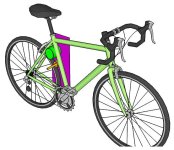
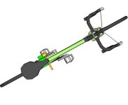
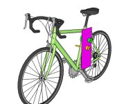
Ok, I doodled in Sketchup for a few minutes with a free bike already available on the warehouse. I still suck at Sketchup, so stuff isn't centered and things overlap, etc. But it gets the idea across.

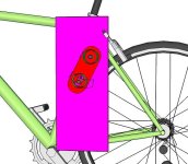
The purple plate is essentially the same thing as my DayGlo Avenger setup's plate. There would be a second one on the right side that is left out for clarity. The plate would be shaped not rectangular but simply use only what is needed to make the suppor to attach to the bike frame. I'd probably use hose clamps if I were to do it again, to hold the brackets for the plate to the frame.

The motor is green, as is it's pulley on the left side of the plate. It is mounted so that it cannot touch the wheel, but does push against the bike frame for extra stiffening. Alternately, it can simply be bolted to both plates, at each end of the motor.

The jackshaft is orange. The pulley on the left side of the plate would be connected to the one on the motor by either belt or chain. Chain is more efficient but it will be noisier. The support/bearing on the other end is not shown, but would be bolted to the right side plate (also not shown), working the same way your existing one does. There would be a bearing just like it on the left end plate.

The drive wheel is the other orange cylinder on the jackshaft, in contact with the tire.

Tension adjustments could be made in a number of ways. It is more complex because you must have a tension adjust for the chain or belt as well as one for the friction drive to wheel.

I would use a curved slot for the jackshaft to move in on both end plates, which would have it's center pivot point the shaft of the motor. The radius would be whatever gets you the best adjustment for tension; I suspect it must be the same as the radius of the circle around the motor at that distance. That would keep whatever tension you set between motor and jackshaft.

The motor-jackshaft tension could be set by an arm (red) that pivots around the motor shaft that actually holds the bearings for the jackshaft. If this is done then the curved slot in the side plate for the jackshaft must be wider than otherwise necessary so that it can be moved radially outward for tensioning the chain/belt.

Once that tension is set, then setting tension against the wheel simply requires pivoting this arm around the motor shaft, and will not affect the motor/jackshaft tension.

Does that make sense?
Friction drive with jackshaft belt 1.png
Friction drive with jackshaft belt2.png
Friction drive with jackshaft belt3.png
Friction drive with jackshaft belt4.png
 
WOW amberwolf, great stuff. What you propose should work and makes perfect sense. I like your tensioning solution as well. Also think your design elliminates the twisting and lateral force issue inherent in mine. Had considered that same approach just positioned differently. This motor is 4" in dia and would not fit (on my bike) that area. Had planned something more like this:

BikeDrive.jpg


This design centers the motor over the bike. What's applealing to me is the ability to remove the drive system easily. I have another saddle and post in the garage. It takes seconds to have my non-motored bike back. But that's only my specific need and application.

Had come to my own conclution that introducing any lenght belt or chain would lead me away from friction drive. Many moving parts and energy losses. What are your thoughts on this?
 
That design would lend itself to an easily installed aftermarket kit - just sell the seat post, motor controller, drive, batteries even as one chunk for the people to swap with their current saddle!
Anyone want to use that idea. I have no patent interest! :D
 
Solar Motion said:
What you propose should work and makes perfect sense. I like your tensioning solution as well. Also think your design elliminates the twisting and lateral force issue inherent in mine. Had considered that same approach just positioned differently. This motor is 4" in dia and would not fit (on my bike) that area. Had planned something more like this:
Well, the problem with that is that it doesn't leave the rack open for cargo and the like. :) Also it puts more weight higher up on the bike. Both of those are reasons I put mine down there. And I have to admit that part of the reason I am suggesting what I am is that it is a solution I'm pondering for using to get DayGlo Avenger or some variant of it back, using a PMDC weedeater motor (or similar) and about 60V worth of NiMH. (I'm also pondering using one of the wheelchair motors with it's gearbox, and driving the bike drivetrain with it via the granny gear)

What you *could* do is to extend the left side plate I describe forward enough to support the motor in the *front* triangle, and belt from there to the jackshaft. Then the motor would still fit in frame lower than it is and leave your rack clear for other stuff, able to be lower to the ground (closer to the wheel), for better balance on the bike with lower COG.

What's applealing to me is the ability to remove the drive system easily. I have another saddle and post in the garage. It takes seconds to have my non-motored bike back. But that's only my specific need and application.
That is definitely a plus, since you could move it from bike to bike quite easily.

Had come to my own conclution that introducing any lenght belt or chain would lead me away from friction drive. Many moving parts and energy losses. What are your thoughts on this?
Friction drive itself has so much energy loss that I would not worry about the tiny bit you'd lose with chain. Bit more with belt drive, but if it's a cogged belt instead of Vbelt it's good enough. More moving parts, yes, and more complicated, heavier. Depends on your purposes and requirements. :)

For me, it needs to be out of the way of the over-wheel space, and as low to the ground as I can get it, so I can carry cargo and balance better. That's one reason the current DayGlo Avenger (and CrazyBike2) have side-frame-mounted cargo pods, centered roughly about the rear axle. DGA also has a rear rack for those many times the pod can't hold enough. (and I never did put the rightside pod on).
 
amberwolf said:
Friction drive itself has so much energy loss that I would not worry about the tiny bit you'd lose with chain.

Not worried about it - just don't agree. Looks like you've got a new build in mind and looking forward to seeing it. Thanks for your "interest" in mine.
 
Not sure why you used quotations marks that way? I am actually interested in your design even just as it is, because I think it's a really simple design, elegant and easy to build, setup, install, and use. For my own purposes it would require rethinking, is all. :) Lots of other people, probably most of them, would be able to use it exactly as it is right now.


As to what I said about friction drive's energy loss, it's mostly from things I observed about it, which might be misinterpreted by me, since I don't know engineering or physics. The rest of it is what I've read that others say about it, that sounds right to me based on my own observations.

Either way, friction drive *does* work and can work very well--my own DayGlo Avenger's second friction drive worked really well, especially considering how it was made and what it was made from. Could probably have been made even better, if I had known what I was doing. :)

Yours probably works way better than mine did, partly because you only have one motor, and so less loss in the bearings, brushes, and other places motors are lossy, plus less weight.
 
I think everyone assumes friction drive has big losses because of the name. "Friction" just sounds like it uses up a lot of energy. lol

From my experience I feel like I'm getting better than average efficiency with my sliding, variable pressure, friction setup.

I also read a lot of negative things about friction drive when I first started getting into e-bikes. I can now say with confidence that most of these comments are total crap. The only issue is if you want to ride in the rain. I don't see how you can make a good friction setup for wet weather and I don't care since I don't ride in it.

I'll even go out on a limb and say friction drive can compete with just about any other setup I've ever seen if done correctly (again, assuming dry conditions).
 
Back
Top