Solar Motion said:
HI Amberwolf, did not know the DayGlo project was your build. Read your articles in detail months ago - great stuff!
Thanks! I actually want to put that back in operation but haven't figured a way to replace the broken shaft on the second motor yet (and it needs both to work).
Good question. It's my understanding that a brushed DC motor can run backwards and provide the same torque+revs per amp. The controller is dictating the current either way, right? Would need to plot a few amps vs. mph data points then mirror motor to the left side and re-run.
Yes, but some motors are designed to run in a specific direction, and the brushes are offset or angled for that purpose. It's common with purpose-designed motors. When this is the case, often they are significantly more efficient in that direction than in the other. So I'm curious as to whether that motor is indeed offset or not.
It is also possible with many (but not all) brushed motors to "advance" the timing of the brushes on the comm bars so that they can be run at significantly higher voltages than designed, without arcing/etc. But when this is done, they don't work very well in the other direction, for the same reasons that they work better in the advanced direction.
The downward pressure is applied by lowering and locking the seat post not the battery weight. The rack is thru-bolted to the seat post. No other lateral supports. Pulling a full trailer up hill w/o pedaling will "twist" the seat post and drive wheel off center. Did this a few times at the beginning, now know where and when to ease off the throttle. Happy it does that. Acts like a pressure release valve preventing larger forces on the motor and drive assembly.
Interesting. Funny how certain side effects wind up desirable like that, where in other situations they'd be a disaster.
Only thing that would worry me about that then is snapping that seatpost at the weak point of the bolt hole thru it.
Placed the drive wheel directly atop keeping weights/pressures parralel to contact with ground. Something seemed right about a straight line between tire on ground and drive on tire.
Makes sense. Simpler physics.

About your description: Jackshaft = arbor? Both friction and chain/belt drive? Would like to know more about your ideas.
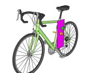
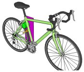
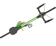
Ok, I doodled in Sketchup for a few minutes with a free bike already available on the warehouse. I still suck at Sketchup, so stuff isn't centered and things overlap, etc. But it gets the idea across.
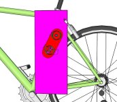
The purple plate is essentially the same thing as my DayGlo Avenger setup's plate. There would be a second one on the right side that is left out for clarity. The plate would be shaped not rectangular but simply use only what is needed to make the suppor to attach to the bike frame. I'd probably use hose clamps if I were to do it again, to hold the brackets for the plate to the frame.
The motor is green, as is it's pulley on the left side of the plate. It is mounted so that it cannot touch the wheel, but does push against the bike frame for extra stiffening. Alternately, it can simply be bolted to both plates, at each end of the motor.
The jackshaft is orange. The pulley on the left side of the plate would be connected to the one on the motor by either belt or chain. Chain is more efficient but it will be noisier. The support/bearing on the other end is not shown, but would be bolted to the right side plate (also not shown), working the same way your existing one does. There would be a bearing just like it on the left end plate.
The drive wheel is the other orange cylinder on the jackshaft, in contact with the tire.
Tension adjustments could be made in a number of ways. It is more complex because you must have a tension adjust for the chain or belt as well as one for the friction drive to wheel.
I would use a curved slot for the jackshaft to move in on both end plates, which would have it's center pivot point the shaft of the motor. The radius would be whatever gets you the best adjustment for tension; I suspect it must be the same as the radius of the circle around the motor at that distance. That would keep whatever tension you set between motor and jackshaft.
The motor-jackshaft tension could be set by an arm (red) that pivots around the motor shaft that actually holds the bearings for the jackshaft. If this is done then the curved slot in the side plate for the jackshaft must be wider than otherwise necessary so that it can be moved radially outward for tensioning the chain/belt.
Once that tension is set, then setting tension against the wheel simply requires pivoting this arm around the motor shaft, and will not affect the motor/jackshaft tension.
Does that make sense?


