crossbreak
1 MW
great find, spinning magnets! thx again!
")
spinningmagnets said:ls7corvete, would you be interested in trading some of your parts (Kepler drive + X) for a guaranteed working drive from me? It would include a Castle Creations ESC, but no battery or throttle. You would have a choice of one out of two 63mm outrunners. A 295-Kv, and a 250-Kv. Since they are driving a one-inch or 1.25-inch roller, they use a higher Kv than the shell drives. The 1.25-inch roller using 22V with a 295-Kv will provide 20-MPH.
The model of Castle ESC can use 28V (8S), and 28V should provide about 25-MPH. A different ESC could run 10S / 37V or...12S / 44V
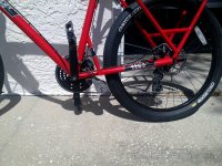
adrian_sm said:Any reason you can't cut a groove for your cables in the seat tube clamp, then mount the friction drive up on the seat tube.
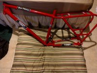
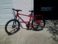
ls7corvete said:Here is an update for you guys, I think things are looking pretty nice here!
Now if they just ran as well as they looked.
BTW you can see my other electric vehicle in the background.