Friction drive opinions.

Joined
Feb 23, 2012
Messages
58
Location
FL, USA
Well I have a kepler Mk1 drive on the way. I am also in the process of ordering a Commuter booster. I am excited to put these things together but now I am stuck on what controller and what batteries to get.

For the controller I was planning on just getting a small and inexpensive sensorless controller (Lyen or winderness energy). But now I am wondering if I should get something that could be put on a more powerful bike in the future?

For batteries, I want 36v so I can use a ebike controller instead of a RC speed control. I cant decide between the 10s Lipo and 2x 6s LiFePO4. I havent found a charger for either of them I am happy about. Hardcase batteries are attractive but I cant figure out a way to make a 36v pack with between 5-8ah (I want a small pack to start with, I will double up later if I need).

What do you guys think?

I will be using this for short trips around town, 5-10 miles mostly. Always pedaling, I just want to get my speed up to between 20-25mph on the flats

Kepler eboost Mk1 drives for sale.
http://endless-sphere.com/forums/viewtopic.php?f=9&t=32035

Commuter Booster drive units.
http://endless-sphere.com/forums/viewtopic.php?f=31&t=34586

C6374-180kv Brushless Outrunner Motor.
http://www.hobbyking.com/hobbyking/store/__13975__C6374_180kv_Brushless_Outrunner_Motor.html

Turnigy 4500mAh 6S2P 30C LiFePo4 Pack
http://www.hobbyking.com/hobbyking/store/__10311__Turnigy_4500mAh_6S2P_30C_LiFePo4_Pack.html

Turnigy nano-tech 5000mah 10S 25~50C Lipo Pack
http://www.hobbyking.com/hobbyking/store/__14609__Turnigy_nano_tech_5000mah_10S_25_50C_Lipo_Pack.html
 
You need to stay with 5S or 6S with both these drives. This is what they are designed for. The motor diameter is too large for a higher cell count. You can always parallel the packs for the friction drive and series them for another project.

My recomendation is that you check out Adrian's excellent shopping list https://sites.google.com/site/commuterbooster/shopping-list

I personally recommend:
2 x 6S 5000mah packs wired in parallel.
63-74 200kv motor
100A ESC

Then you need to sort out the interface. Lots of threads on this.

Good luck. I am sure you will have a good time with these drives.
 
Listen to Kepler.
you need to understand the relationship between voltage, motor KV, motor diameter, and road speed.
Your proposed 36v set up would be running up to 40-45 mph !
Keeping to the 6s configuration will simplify your charger choice too
And if you want to avoid a lot of grief, use a Castle Creations controller from the start ( with extra caps) ! :wink:
 
Totally agree with Kepler. 36v is too high for the 63mm 200kv motors we both recommend. But *might* be alright with this motor.
http://www.hobbyking.com/hobbyking/store/__18184__Turnigy_Aerodrive_SK3_6374_149kv_Brushless_Outrunner_Motor.html
It is 59mm diam, a lower kv, and supposedly higher efficiency.

Controllers:
Lyen is the only person I know that is running my drive with a sensorless ebike controller, but I have not got a full account of how it is going. It took him quite some time to get it up and running for some reason. I would love to hear more about why. I suspect it is mainly around poor initial startup, and drive engagement.

Both Kepler's and my designs use some additional electronics smarts in addition to the RC-ESCs to control throttle ramp up rates, enforce a minimum speed , and maybe one or two other tricks :wink: to mainly to smooth drive engagement and keep ESC and motor happy. This is something the ebikes controllers don't do.

I recommend with both Kepler's and my drives to initially stick with the ESCs and throttle interfaces that we each offer, or an CA-LRC if you want a twist throttle. We have both spent a lot of time and effort researching, designing, improving, refining the designs to offer what we have now. Sure some of the trades offs we made, may not match your needs, but at least you aren't entering a phase of research, rather you should be just enjoying the new drive.

Batteries:
Another advantage of running 5-6s LiPo and RC-ESCs are the ease of charging. Just parallel the packs, and hook them up to any old RC charger to charge and balance every charge. Really easy to expand pack size later too.

At 10s there are charges capable of 10s charging the Hyperion one I think. But pricey. You could always parallel them to charger, and series them to use. This can be done at the battery connection, with judicious use of anderson connectors.

I know the ebike controllers have been modified for running at 20-24V, so you shouldn't need to go to 36V just to get an ebike controller. Speak to Lyen.

Hope that helps,

Adrian

P.S. Now I better get back to getting all the Commuter Boosters out to everyone. :D
 
Hillhater said:
Listen to Kepler.
you need to understand the relationship between voltage, motor KV, motor diameter, and road speed.
Your proposed 36v set up would be running up to 40-45 mph !
Keeping to the 6s configuration will simplify your charger choice too
And if you want to avoid a lot of grief, use a Castle Creations controller from the start ( with extra caps) ! :wink:

this is good info. voltage, motor kv, motor diameter and road speed will play a giant role in how you set up a FD. you have to take those things into account with kepler's and adrian's FD systems. if it was a friction roller, you can just change the size of the roller.

i went the latter and didnt use a castle creation controller. from all of the money ive spent, i couldve bought a castle creations and saved myself the grief. but all that is history and you learn from your mistakes. :lol:
 
This post may be useful in selecting components for a friction drive:
http://www.endless-sphere.com/forums/viewtopic.php?f=31&t=34586&p=536778#p536778

Key point on relationship between volts, diam and kv.

A quick equation for the no load speed is:
kph = battery volts * motor diam in mm * motor KV / 5305
mph = battery volts * motor diam in mm * motor KV / 8538

Note: The no load speed is where the motor provides no work, so for the real assist speed drop this number down a bit, and calculate it at the depleted battery voltage.
 
If you run 36V (or more), then, when you are running at 20-MPH (probably most of the time), you will be at half-throttle. That is bad for the controller. You should spend most of your time near full-throttle, so the controller will run cooler.

There have been problems in the past running E-bike controllers with certain RC motors because of the pole-count, so choose carefully if you are determined to avoid an ESC. First, you have to add sensors (usually halls, mounted on the inside, NOT on the shell), or possibly one of Berties optical sensor kits. Lyen makes a good sensorless controller for hubs, but it has issues with RC motors.

If you want to experiment, fine, I definitely understand the fun. Lots of people have fried a lot of parts playing with these (I have, yes it was fun), but,...there comes a certain point where theres really not much new that can be discovered. Trust Kepler and Adrian.

I advise a Castle Creations ESC, and add 4 of the 50V capacitors. The ICE-100 should work well. It will run 5S/6S (18V/22V) which is recommended for either of your drives. It will also run up to a max of 8s (28V) if you want to experiment with a higher top speed, but the ESC may hot on the hills. I have tried 4 ESCs, and I run the Castle. http://www.castlecreations.com/products/phoenix_ice.html
 
Totally agree with Kepler. 36v is too high for the 63mm 200kv motors we both recommend. But *might* be alright with this motor.
http://www.hobbyking.com/hobbyking/stor ... Motor.html
It is 59mm diam, a lower kv, and supposedly higher efficiency.
Yes that gets me much closer to where I want to be!

@def215 and spinningmagnets: I will certainly grab a castlecreations if Lyen cant come up with something else for me. I will PM him and see what he suggests.

The Hardcase batteries are looking more attractive.
 
The Turnigy Aerodrive motor (63mm dia/74mm length) with the low kV of 149 is a new development. I don't know of anyone who has tried it yet, and I don't know how it will work at 36V. If you get it, I will be very interested to hear how it works out. I'd also like to hear how it runs on 6S (top speed at that kV)

The Castle Creations ESCs that can use 36V can use between 18V-50V and are the "HV" line (more expensive). You will only need two of the additional 50V capacitors, since the higher voltage means the motor won't bog down as much. http://www.castlecreations.com/products/phoenix-ice2-hv.html

If you can only source a new one, perhaps get the HV-120, but if you can find a used one, there is an 110-amp unit they were still making until recently. Heres one EBAY example listed for $99 http://www.ebay.com/itm/Castle-Creations-Phoenix-HV-110-High-Voltage-Brushless-ESC-New-in-Package-/280839934643?pt=Radio_Control_Parts_Accessories&hash=item41635d52b3
 
Here is a link to a post & thread regarding the SK3s. And more specifically my experiences with the 6364-190kv motors.
http://endless-sphere.com/forums/viewtopic.php?f=30&t=31689&start=15#p539525

They have been pretty good so far. No problems to report.

- Adrian
 
I don't know if this has been mentioned yet, but...for an FD that uses the motor-shell as the drive surface, you need an outrunner that has a skirt bearing. Not all of them do.

This is just one of the dozen reasons to stick with component combinations that are proven, and then listed by Kepler and Adrian. Adrian, you mentioned the 63-74 that has the new low kV of 149,...does it have a skirt bearing? (ls7corvete, in the pic, its the large-diameter ring around the OD on the left).

images
 
spinningmagnets said:
Adrian, you mentioned the 63-74 that has the new low kV of 149, does it have a skirt bearing?

Yes. If the can has screws on it is the usual give away. [EDIT: Because that is what holds the skirts to the can]
http://www.hobbyking.com/hobbyking/store/__18184__Turnigy_Aerodrive_SK3_6374_149kv_Brushless_Outrunner_Motor.html
18184.jpg


But the design is a bit different. The skirt bearing has a smaller OD, and now has fan blades between the bearing and the outer can.
Plus the can now has a few cooling slots in it.

You can sort of see the fan/skirt support for the 6364 motor in these pics.
file.php

file.php


The down side it this makes it much hard to get halls or a temperature probe mounted compared to the larger diameter skirt bearings. Otherwise I would have a heap of temperature data from riding around with this motor versus the EMP-C6374-200kv.
 
spinningmagnets said:
There have been problems in the past running E-bike controllers with certain RC motors because of the pole-count, so choose carefully if you are determined to avoid an ESC. First, you have to add sensors (usually halls, mounted on the inside, NOT on the shell), or possibly one of Berties optical sensor kits. Lyen makes a good sensorless controller for hubs, but it has issues with RC motors.

Why not outside the shell? Lyen has pointed me here, http://endless-sphere.com/forums/viewtopic.php?f=30&t=15686&hilit=gwhy+hall&start=315#p538862, and gwhy seems to be having success with his kit.

This guy seems to have some luck with cheap ebay controllers and RC motors. http://www.youtube.com/watch?v=HLEkBEphL3s. Sorry cant find the original thread atm. That would be a cheap experiment.

Lyen's controllers will work with 8s which seems to be the way to go (can always re-wire for 4s if all else fails). Adding hall sensors using gwhy's kit seems to be the way to go, though currently that limits me to 63mm motors and again the problem of a 40mph no load speed comes up.
 
Thud had problems running external halls when using higher voltages, the internal hall mounting works without any regard to what voltage you are using. If you are running 48V or less, it probably won't be an issue.

If you are using 28V or less, the ESCs seem to be reasonably affordable, but when you bump up to the next tier, where the ESCs can use from 18V to 50V, they get pricey. The popular and well-regarded HV-160 is usually over $220.

I had the impression from what I had been reading on ES a while back, that the push to add halls to RC motors (there are several potential benefits) is to affordably run 36V or more. Halls also greatly help running the motor slow on an offroad uphill.
 
The main problems what people were having with adding halls to the outside of a motor was spacing and placement the problems were also tied into what power levels the motors are being run at, I have spent quite a bit of time getting the external sensor modules working 100% which I have now achieved. The cheap (modified) e-bike controllers work very well when the hall sensors are setup correctly. I still have not damaged a e-bike controller whilst it has been running one of my bikes and typical reliable power levels for the way I that I modify my e-bike controllers are 3-4kw for a 6fet and 5-6kw for a 12fet at these power levels ( or higher ) it is essential that the halls/timing are setup spot on.
 
gwhy! said:
The main problems what people were having with adding halls to the outside of a motor was spacing and placement the problems were also tied into what power levels the motors are being run at, I have spent quite a bit of time getting the external sensor modules working 100% which I have now achieved. The cheap (modified) e-bike controllers work very well when the hall sensors are setup correctly. I still have not damaged a e-bike controller whilst it has been running one of my bikes and typical reliable power levels for the way I that I modify my e-bike controllers are 3-4kw for a 6fet and 5-6kw for a 12fet at these power levels ( or higher ) it is essential that the halls/timing are setup spot on.
I will only be running about 600w so I am not sure what I can get away with.

I would like to talk you into making a 59mm kit ;) but I have messaged Burtie regarding his optical boards as well.
 
ls7corvete said:
gwhy! said:
The main problems what people were having with adding halls to the outside of a motor was spacing and placement the problems were also tied into what power levels the motors are being run at, I have spent quite a bit of time getting the external sensor modules working 100% which I have now achieved. The cheap (modified) e-bike controllers work very well when the hall sensors are setup correctly. I still have not damaged a e-bike controller whilst it has been running one of my bikes and typical reliable power levels for the way I that I modify my e-bike controllers are 3-4kw for a 6fet and 5-6kw for a 12fet at these power levels ( or higher ) it is essential that the halls/timing are setup spot on.
I will only be running about 600w so I am not sure what I can get away with.

I would like to talk you into making a 59mm kit ;) but I have messaged Burtie regarding his optical boards as well.

I dont have a 59mm motor to test a hall setup with but I will have a play to see if you can get away with a sensor for a 63mm motor. The optical sensors will work just as well as halls but im guessing you want this for a friction drive and there may be some issues using a optical setup with keeping it all clean.
 
gwhy! said:
I dont have a 59mm motor to test a hall setup with but I will have a play to see if you can get away with a sensor for a 63mm motor. The optical sensors will work just as well as halls but im guessing you want this for a friction drive and there may be some issues using a optical setup with keeping it all clean.
Yea would have to make something to cover the thing and keep it clean. Not a challenging design but something to make note of.
 
ls7corvete said:
Yea would have to make something to cover the thing and keep it clean. Not a challenging design but something to make note of.
Remember , the sensors are close to the can, the can is riding on the tire, and the tire is rolling on the road surface...picking up any dirt, dust , moisture, and other debris that may be lying there !
so the tire could easily pick up a piece of gum, transfer it to the can, which then stuffs it into the Halls ! :cry:
I am not aware of anyone who has run a direct FD ( motor can on the tire ) , with external halls ??
 
I briefly tried a sensored (internal halls) can-on-motor friction drive with a 80100. But it was a borrowed motor & controller and was not setup properly for my voltage, so the resulting power levels were disappointing.

I love the look of gwhy's external halls, and would be interested to see how it performs on a friction drive with ebike controller. I can just see them being mounted on the inside of my swing arm, assuming I ahd enough radial clearance to the pivot block.

If I was to go optical, I would be tempted to make it a rotary encoder on the motor shaft. On my friction drive design it would be pretty easy to have the motor shaft protrude through the swing arm, mount the encoder wheel on its end, then mount sensor/s on the swing arm itself. Finally a nice little opaque cover to keep the sunlight from stuffing the signal. Could all be done very neatly.

But at the end of the day, I couldn't be bothered with sensors as I don't see a real advantage for a friction drive at least not on my design. Unless you are looking for >1kw power levels. But I would argue hub motors are probably a better solution then. It would make more sense on the permanently engaged friction roller design, as it would allow you to power up from a dead stop reliably. But the disengaged swing in style friction drive doesn't like hitting a stationary tire much.

I'll stick with my tiny, light, cheap, and so far very reliable RC ESCs thanks.
 
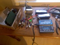
Well I am currently at a loss as to where to go from here. I just do not have the motivation to mess with DIY at the moment. Just messing with the anderson connectors is pissing me off- time to go back to deans. So here are some thoughts.

So right now I have:
Both Kepler's and Adrian's friction drive units
6374-149kv (59mm diameter)- Note does not fit Kepler's drive
One optical hall sensor board
Two 4c 4.5ah Hardcase batteries and one charger
Cheap 24v 500w Ebay controller
Thumb throttle

So I am guessing most people would still recommend grabbing a CA-LRC and RC ESC. Though another option would be to try and swap my 6374+optical board for a 50mm drive (anyone have one with halls?) and try to run with the cheap speed control. Right now I am leaning towards using the Kepler drive as I am tired of messing with this and having everything more or less contained to the seat post sounds great.

I do have two friction drives at the moment so swaping one out will give me some $ for parts. I really just want the easiest way to get this thing setup, or swapped out for an easier kit to setup.
 

Attachments

  • IMG_20120821_194147.jpg
    IMG_20120821_194147.jpg
    75.4 KB · Views: 5,286
Easy way for my kit is to follow the standard installations instructions. www.commuterbooster.com. But I think you decided not to buy the Brain Box from me, so signed yourself up for DIY approach.

Now lets see what you can do with what you have. With a 149kv 59mm motor, it will only have a slow 25kph no load speed at 4s voltages. So if you are to stick with that motor, I would recommend you run it at 8s. This will give you something closer to 50kph no load speed, which is closer to how I recommend you set up my kit usually. (Note: I usually run 5s on a ~200kv motor)

Question is whether your cheap controller can handle 8s LiPo voltages, which is 33.6V hot off the charger. If it does and you know how to install the optical hall sensor board, you should be able to hook everything up.

- Adrian
 
Well I have put together the kit. I am using a Castle Creations Mamba.

I am running 8s, a 149kv 6374 and am getting <13mph top speed with <100w of power(when cruising, higher on acceleration). CA is seeing full throttle.

I am clueless to what the problem is, no load speed should be almost triple what I am getting.
 
Just messing with the anderson connectors is pissing me off- time to go back to deans

I really like the XT60 connectors, and they now have a slightly larger version called XT90. Easy to solder wire to, and then heat-shrink. edit, the XT60s use 4mm bullets, and are rated for 60A, and the XT90s use 5mm bullets and are rated for 90A. I like how theXT housing holds the pins straight, and some other housings I tried sometimes allowed the pins to wobble around, so i had to jiggle the male/female housings to get them to mate properly.

http://www.hobbyking.com/hobbyking/...0_Connectors_Male_Female_5_pairs_GENUINE.html
http://www.hobbyking.com/hobbyking/store/__24707__Nylon_XT90_Connectors_Male_Female_5_pairs_.html
file.php
 
Back
Top