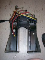
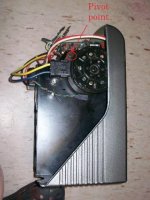
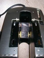
Friction drive outrunner setup. New DJ bike.

John in CR said:
Please explain the traction belt/friction drive. Do you mean something like typical on a riding lawnmower deck, with a lever to engage the belt with the pulleys?

John

i wanted to gain traction, not loose it in some kind of slipping belt clutch. no i meant what i said, a traction drive like those used by tanks, heavy equipment, etc. you know that thingie with the caterpillar treads.

the idea was to increase the contact area with the tire and to do it with a rubber surface to reduce slipping when wet. at first i thought of adding a molded rubber surface to the outside of the drive roller. but that would not significantly increase the surface area. inspiration came when i was playing with a friends Bren Gun Carrier. i was impressed by how the tracks would mold and conform to the terrain.
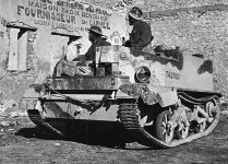
bren-gun-625x450.jpg

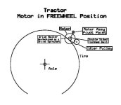
so i came up with this design:

traction-freewheel.jpg

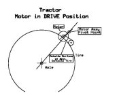
the idler pulley is fixed in relation to the motor and pivots together with the motor. a 2"wide double sided conveyor belt was used. in the drive position:

traction-drive.jpg

now i had a big long driving surface contacting the tire. the belt i used had very thin grooves on the outside so it did not shed water as well as i had expected. but it was still better than the raw roller when wet. worked very well though in dry conditions. also improved the grip with sandy surfaces.

if i had continued, version 2 would have used a double sided 5mm pitch belt of some kind. most likely a pair of 15mm wide ones side by side.

rick
 
OT here but it is entertaining. for those who care yes i do know someone who actually owns a Bren Gun Carrier. and i was driving it on his farm when i got the idea. he even has a pair of Bren Guns to go with it. (registered as a collector, yes they are fully operable, no they are never mounted on the vehicle, they sit in a display case that doubles as a coffee table in his living room.)

these things were used by the British, Canadian and Australians during WWII. on the home front the Americans had "Rosie the Riveter". the Canadian cultural equivalent was "Ronnie the Bren Gun Girl"
26683854.brengrl3.jpg
VeronicaFoster-RonnieBrenGunGirl-smoke.jpg

see - guns and babes isn't a new idea. dates back at least to the 1940's and possibly is a Canadian invention.

i will now cower and await the wrath of the moderators.

rick
 
rkosiorek said:
John in CR said:
Please explain the traction belt/friction drive. Do you mean something like typical on a riding lawnmower deck, with a lever to engage the belt with the pulleys?

John

i wanted to gain traction, not loose it in some kind of slipping belt clutch. no i meant what i said, a traction drive like those used by tanks, heavy equipment, etc. you know that thingie with the caterpillar treads.

the idea was to increase the contact area with the tire and to do it with a rubber surface to reduce slipping when wet. at first i thought of adding a molded rubber surface to the outside of the drive roller. but that would not significantly increase the surface area. inspiration came when i was playing with a friends Bren Gun Carrier. i was impressed by how the tracks would mold and conform to the terrain.


so i came up with this design:
the idler pulley is fixed in relation to the motor and pivots together with the motor. a 2"wide double sided conveyor belt was used. in the drive position:
now i had a big long driving surface contacting the tire. the belt i used had very thin grooves on the outside so it did not shed water as well as i had expected. but it was still better than the raw roller when wet. worked very well though in dry conditions. also improved the grip with sandy surfaces.

if i had continued, version 2 would have used a double sided 5mm pitch belt of some kind. most likely a pair of 15mm wide ones side by side.

rick


That is a rather brilliant variation on a drive roller! My own brief investigation of friction drive stopped after I realized I'd crush my tire using a small diameter roller and self activating tensioning system at more than a few hundred watts. I think I could even adapt the Rolamite mechanism I was thinking of using. This requires more investigation.

Lawson
 
My current plan is to modify my mount to slide (rather than pivot) back into the tire. This simple modification has me even more excited about friction drive. I've been very happy with my drive anyway but I'm hoping to get to the point of being able to pop wheelies with throttle only. That would stop people from ragging on friction drive (yeah, right). :lol:

John, I'm not sure a non-freewheeling roller would work in this case. The roller would have to at least touch the tire in order to engage when you apply throttle.
 
here are some pictures of an early proof of concept Tractor Drive. this was the first version with the motors and belt locked into a fixed position. i was more interested in prooving that the belt would actually grab the tire and work when wet.

CW Motor-LHS.jpgRear View.jpgCCW Motor-RHS.jpgTractor.jpg

in this version the motors and belt do not pivot. it was adjusted so the tire would contact between the drive roller and the nylon rollers making up the back end of the tractor belt. this was just a quick and dirty test that did not require any modification to the basic motor assembly. this proved to me that i had the driven end of the tractor belt the wrong way around. i later built a second version with the arrangement shown in the scketches.

the big empty spaces below the motors is where the 18Ah SLA Batteries were stored.

sorry but i have not found any photos of that arangement. i also have not found that drive unit in my storage unit. this earlier experimental unit is about to be dis-assembled and the motors/tractor belt scavenged for parts to build a dyno.

rick
 
MY first e-bike drive many years back used a rubber belt around 2 rollers which was lowered onto the front tyre (Zeta2). The motor was about 150W, ran off 12V SLA, and it was very noisy and didn't work particularly well.
 
Grinhill said:
MY first e-bike drive many years back used a rubber belt around 2 rollers which was lowered onto the front tyre (Zeta2). The motor was about 150W, ran off 12V SLA, and it was very noisy and didn't work particularly well.

not a very constructive or informative critique. sounds like the typical dismissive attitude towards friction drive in general. specifically why did you find the Zeta2 not very good?

150W too little power? not enough RPM from 12V? whole thing was just too flimsy to maintain proper contact with the tire? it tossed belts all the time? the belt did not provide enough friction? if so why? Were Your expectactions from a 12V 150W motor were too high and so anything short of 50Kph and 100Km range was disappointing? it didn't live up to the makers/ marketers hype? Specifically what did you find at fault?

I learned of the Zeta2 long after i tried my experiments from a discussion with Juergen at Acclivity Solutions in Ottawa. he still has one of those units. after some research the information i found was that the Zeta2 was just another Clive Sinclair creation/failure. a fundamentaly good idea, very pooly and cheaply executed that ultimatetly failed because of its poor construction and design comrpomises. it suffered from all of the problems listed in the previous paragraph and many others. the blame should be put more on that huckster Sir Sinclair and crappy design/build quality than on the basic idea it was based on.

rick

BTW the EV-Warrior has only a slightly better pedigree as far as hucksters go. it was designed by Malcolm Bricklin and Malcolm Currie. but al least they hired real engineers to do the design and invested some money in doing it right.
 
I used to get annoyed when everyone dismissed friction drive but now I don't care. I know it works great if you do it right. I love the fact that I've made a 30 mph bike for very little money. Like I said before... I've had a couple of local guys that have hub motors want me to build them a drive after trying my bike. I think this pivoting idea will be the icing on the cake if I can figure out a simple way to implement it into my design.
 
sounds like the typical dismissive attitude towards friction drive in general.
Not at all. I should have stated that a belt system would not necessarily be superior to the roller just by virtue of the contact area, and I used the Zeta2 as an example.

specifically why did you find the Zeta2 not very good?
Covered very well in all those points your post. I didn't want to delve too far into ancient history on someone else's thread.

Maybe the flimsiness of the support structure meant that insufficient force was applied to the tyre?
 
Ok... I just started working on a simple sliding mount for my drive... Rkosiorek, you mentioned that the EV Warrior roller moved in about 1/8 of an inch when it was engaged. Do you think that's enough total movement? I suppose it depends on how far past center of the tire you mount the drive. I thought about starting with 1/4" of total movement since I'm using this on a rack that will probably have a little flex when the roller engages.
 
the motors move more than that. but when locked into the drive position they only bite about 1/8" to 3/16" into the tire. how far it travels to get there is up to you.

digging into the tire any more that 1/8" and more energy is wasted deforming the tire than in propulsion.

rick
 
rkosiorek said:
the motors move more than that. but when locked into the drive position they only bite about 1/8" to 3/16" into the tire. how far it travels to get there is up to you.

digging into the tire any more that 1/8" and more energy is wasted deforming the tire than in propulsion.

rick

Thanks. I'll try a few different things until I get a distance that works. The nice thing about the slide I'm making is that I can simply machine a longer groove to get more movement.

I'm going to try to get it working early this week. If I do I'll get some pictures up (I know, I'm bad about getting pictures posted).
 
As usual I'm about a week behind on all of my projects. I got the first version of my sliding mount done tonight. I made it slide 1/4" from the loose non-drive point to the engaged point. It works good. It slides back when I apply throttle and it pops back forward when I stop accelerating. To be honest it's not a huge difference from what I had before. I think I need to play around with mounting it further forward so it bites into a higher location on the tire when it slides back.
 
the main freason for having the roller move is not to improve the bite into the tire. it is more to improve the freewheeling when not under power. it decreases the friction and effort required to pedal the bike.

how well the roller bites into the tire depends on it's position (and you may have had it locked into a pretty good position originally) tire pressure, tire compound and tread pattern.

did the ridability of the bike improve after your modification?

rick
 
Rick,

Since I've been using friction drive for quite a while now I have gotten used to about how much pressure I need to have a good compromise between freewheeling and having enough pressure on the roller. I can see the moving mount helping with freewheeling but I'm confident it can increase bite on the tire too once I get it set up correctly.

To answer your question there wasn't a huge difference either way really. I generally set my roller up without too much pressure in the first place so freewheeling was about the same.

Even if it doesn't work I can simply remove the moving plate I made and go back to a solid mount. It's been a fun little experiment either way.
 
don't ditch it yet. the moving motor allows for some variation in tire pressure and tire wear so it should result in a reduced maintenance schedule.

rick
 
Todd,
I would love to see some pics of your sliding mount I'm not really sure how it works. Is it manual engagement or does it somehow torque itself onto the tire? Matt was saying his friend had a leading linkage setup, is that what this is, or at least the same principle? I wanted to do a leading linkage using flexible carbon rods ( golf club shaft) that would bit into the tire the more torque applied, not sure it would work though. For doing wheelies, I wanted to take a roller and apply e medium hard epoxy that had the tire tread pattern match up the grooves. I also found a training slick for roller trainers that has a long wear compound. Maybe you could use something like this and apply more roller pressure whenever you wanted better acceleration. Just my 2cents.

I still wanna see a super stealth/ lightweight street version. Anybody?
 
etard said:
Todd,
I would love to see some pics of your sliding mount I'm not really sure how it works. Is it manual engagement or does it somehow torque itself onto the tire? Matt was saying his friend had a leading linkage setup, is that what this is, or at least the same principle? I wanted to do a leading linkage using flexible carbon rods ( golf club shaft) that would bit into the tire the more torque applied, not sure it would work though. For doing wheelies, I wanted to take a roller and apply e medium hard epoxy that had the tire tread pattern match up the grooves. I also found a training slick for roller trainers that has a long wear compound. Maybe you could use something like this and apply more roller pressure whenever you wanted better acceleration. Just my 2cents.

I still wanna see a super stealth/ lightweight street version. Anybody?

Mine slides further into the tire automatically. It's similar to the ev warrior system but mine slides instead of pivots. I'm currently at work but I'll try to get some pictures up a little later tonight.
 
Ok. Couple of pictures...

This is the mount as it would be in the freewheel position almost off the tire:

3790703600_1231ac989f_o.jpg


When the you apply throttle the motor will slide back into the tire as in this picture:

3789889939_f5a4d3673f_o.jpg


I machined a track for the two pieces to slide on and I filled that with synthetic grease. I may eventually use valve lapping compound to make sure the two mate up perfectly but it's pretty smooth now. There are steel spacers under the washers that stop the pieces from locking together when you tighten the bolts.

I hope that helps explain how it works. I'll post a couple of shots of it on the bike shortly.
 
recumpence said:
Looks good!

I am glad you are using grease. I was going to point out that aluminum will gall and lock up against aluminum.

Matt

True but it's nowhere near that tight of a fit. The channel is more to ensure it can't possibly move too far to one side. I would have rather had the bolts and spacers arranged front to back to avoid using the channel at all but it was just easier this way since I already had it set up for the rack it mounts on.

Actually, I use a Maxnc mill for some of the small work I do (yeah, I know, everyone hates Maxnc but the one I have is far from stock) and the ways and gibbs are aluminum on aluminum. I have thousands of hours on it with no visible wear at all. I just use white lithium grease on that machine.
 
I had some free time tonight to do a little more testing on the sliding mount. I moved it several inches forward on the rack so it sits much lower on the tire. It works great now. When you're off throttle the roller barely touches the tire and I'm positive if I machined longer slots into the sliding plate that I could pull wheelies with throttle only.

Now that my shoulder is feeling better every day it's time to start putting some real miles on this setup to see how everything holds up.
 
Seems like goped copied you :lol:

CloseUp1copy.jpg


http://www.goped.com/Products/GoBike/default.asp
Well not exactly, they list it does freewheel.

I really like how simple this type of kit is, it would be great for my flat bar road bike, earlier I made a non freewheel friction drive (ala: freestyle peg), the motor could swing into the tire and gave plenty of traction, although impressed by the performance I abandoned the project. Now I'm looking to revisit with these new rack based friction systems and I would like your ideas on freewheeling. My previous friction drive was single sided (unlike your roller supported from both sides plus you have no load on the motor bearings) and the motor bearings took all the pressure, it seemd to work although I didn't put many Ks on it nor was it very powerfull.
So my question is would an quality bearing designed into the motor-mount be enough to allow the motor and accociated hardware to survive a single sided freewheeling friction drive? Any suggestions how a one way bearing could be used directly as a traction roller or a simple way of attaching a roller to a one way bearing?? The tire is not wide(700x28) so I could get the motor in close to reduce the load. Anyway just thought Id put it out there and hopefully get some answers.

I'm soooo envious, well done :mrgreen:
 
Two ideas for friction drive in general (I've no idea if they've been suggested elsewhere already):
1. Would there be an advantage in making your drive roller capstan shaped ( waisted as it were) so that more of it touches the tyre?
2. I don't know how you "engage drive" - do you drop the spinning drive roller on the tyre, or does it have to be in contact before you fire it up? If you drop it on the tire, would it be possible to sense the rotation of the drive roller and use that message to trigger engagement of the drive?
Just my 2 pence.
 
I thought as a general rule, friction drives didn't work in the rain. But yet,

With only two moving parts, a drive roller to the rear tire that works in the rain eliminates the need for heavier and complex chains, belts, or complicated and difficult to install hub motors.

What makes this the exception? Is it that quality friction drives will work in the rain upto some amount of power before slipping and this kit is relatively low powered, or are most of the other friction drives out there inferior in some way?
 
Back
Top